So I finally got out in the garage yesterday!
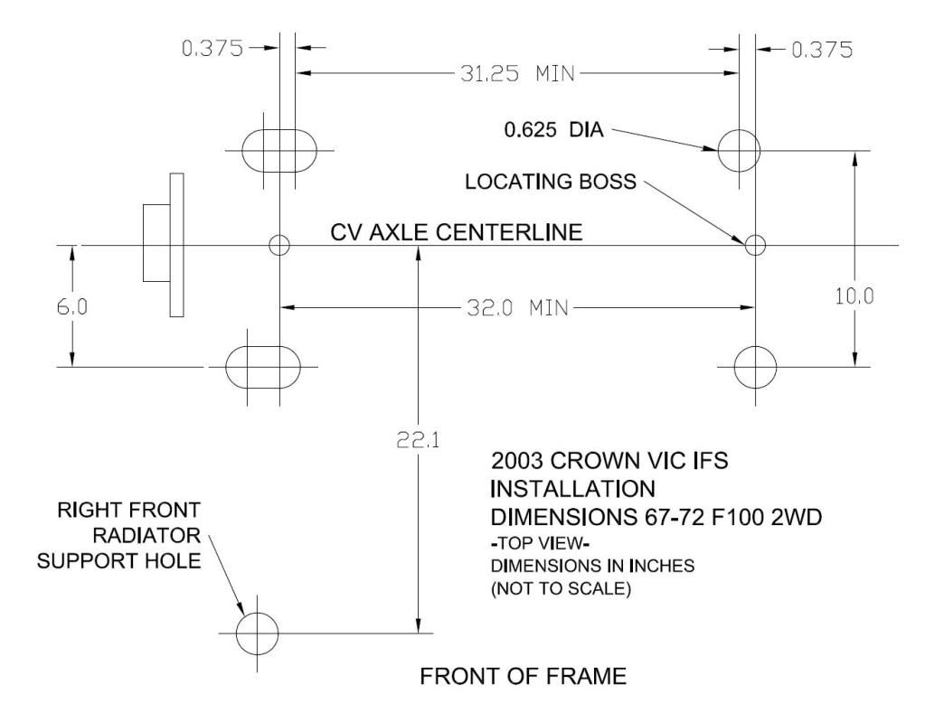
Had read a guy's post on Fordification that showed the measurements for how he set up a pair of boards to sit atop & under the frame rails - sandwiching the rails so that the holes all lined up. Sounded like a great way to go, so I had drawn templates up in AutoCad, measured & taped them to the wood, used a center punch to mark the wood, drilled the pilot holes & then started to line them up to mark & drill the frame rails.


Guess what? The dimensions on his front end differ from mine!
My alignment pins are 31.5" tip to tip. His were 32". Nothing lined up!
Here's his diagram:
http://i649.photobucket.com/albums/uu22 ... NSTALL.jpg
I'm reworking mine & will post the files as pdf's so anyone following in my footsteps should )theoretically) be able to print them out & use them.
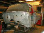
At least I did get something accomplished. I sliced & diced the CV framerail stubs to get the "tubes" out.

I used a shelf standard as a straight edge and cut the frame rail leaving the metal strip intact:

Now when I drill the upper rail with the hole saw, the tubes will drop right in & I can box from the CV rail slice down to the 63 rails...

Seems like a lot of effort, but they're factory, were essentially "free" since I scrapped the car, and what most folks don't realize is - they're threaded! The top of the factory tubes are threaded, and those big factory bolts run up through the bottom of the CV crossmember, into the tubes & thread into the top of these tubes. The factory cap nuts are just lock nuts. The installation should be stronger for it, I think....
Going to finalize my drawings & redo the wood sandwich & drill the rails this morning.
I also came up with an idea on how I'm going to address the rear control arm mounts. More on that later...


