Info for Mark VIII installers

Got a helpful tip or trick related to your slick? Please share...

Moderators: Kid, Casey 65

Post Reply
User avatar
kstones63
Posts: 1504
Joined: April 7, 2007, 10:55 pm
Location: Phoenix, AZ
United States of America

Info for Mark VIII installers

Post by kstones63 »

I don't know who might be able to use this but I will post it for anybody that is doing a Mark VIII engine swap.
These are the descriptions of where the wires go to coming out of the 42 pin connector at the engine and the pin numbers at the EEC. I spent a bunch hours with a continuity tester tracing them out so it might save somebody a bunch of time. It sure made the job easier.
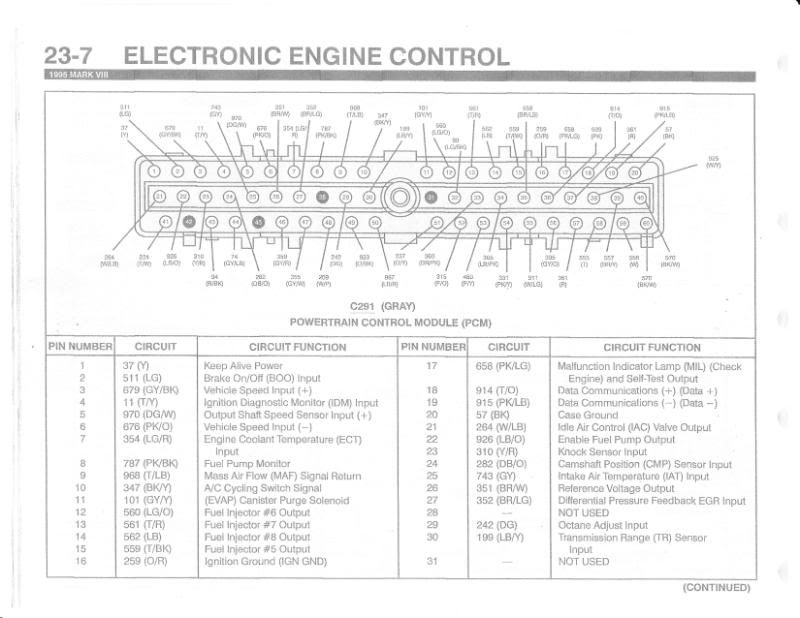
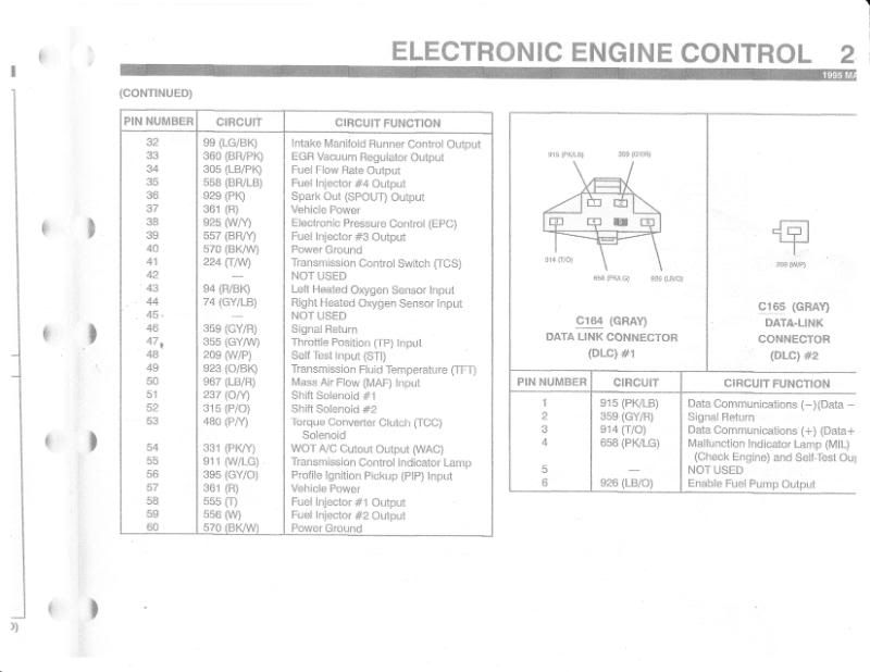
This is the computer (EEC) wiring schematic.
Image
Image

Here is the 42 pin connector
Image

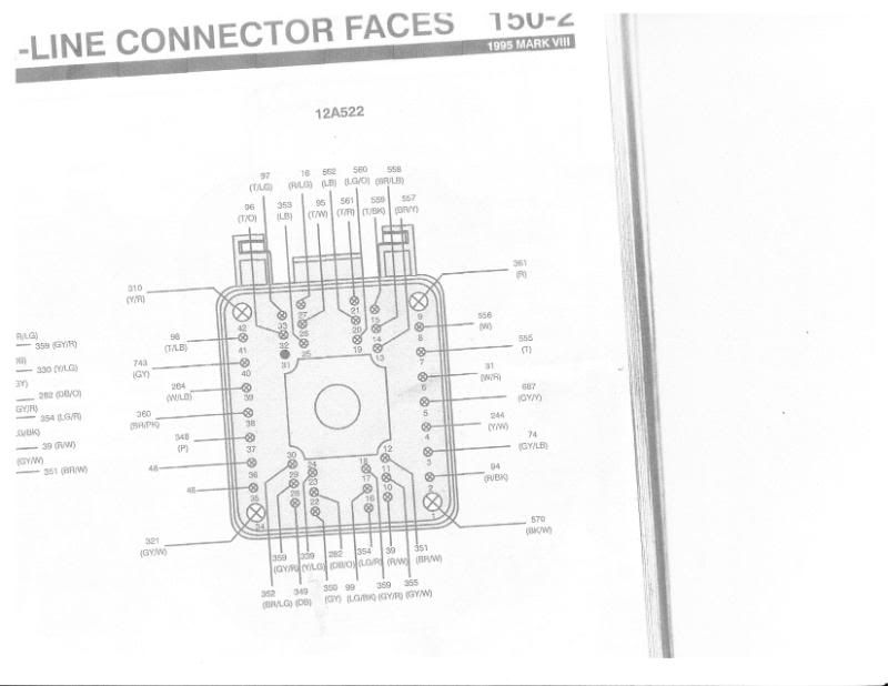
This is my description of where they all go.
42 Pin Connector From Engine Harness
For 95 Lincoln Mark VIII Plug # C118M

PIN / on engine – goes to
#1 - L & R O2 sensors – goes to EEC pin # 60, tees off to power ground and air filter box sensor

#2 – Left O2 sensor – goes to EEC pin # 43

#3 – Right O2 sensor – goes to EEC pin # 44

#4 – Sending unit on back of right head goes to cold lockout for A/C controls. I will change the sensor to a sending
unit for the electric fan relay.

#5 – L & R O2 sensors – goes to switched power supply

#6 – Oil pressure sending unit – goes to gauge

#7 – Fuel injector # 1 – goes to EEC pin # 58 injector # 1 output

#8 – Fuel injector # 2 – goes to EEC pin # 59 injector # 2 output

#9 – Multiple pieces on engine - Vehicle power goes EEC pin # 37 & 57, tees off ignition control module pin # 7
and the main transmission plug on the passenger side

#10 – Temperature sending unit, drivers side – goes to gauge

#11 – Throttle position sensor – goes to EEC pin # 47 throttle position input

#12 – Throttle position sensor – goes to EEC pin # 26 reference voltage output

#13 – Fuel injector # 3 – goes to EEC pin # 39 injector # 3 output

#14 – Fuel injector # 4 – goes to EEC pin # 35 injector # 4 output

#15 – Fuel injector # 5 – goes to EEC pin # 15 injector # 5 output

#16 – Temperature sending unit – goes to EEC pin # 7 engine coolant temp

#17 – Switch on left valve cover – goes to EEC pin # 32 intake manifold runner control output

#18 – L & R O2 sensors, engine temp sender, & throttle position sensor – goes to EEC pin # 24,29 & 46

#19 – Fuel injector # 6 – goes to EEC pin # 12 injector # 6 output

#20 – Fuel injector # 7 – goes to EEC pin # 13 injector # 7 output

#21 – Fuel injector # 8 – goes to EEC pin # 14 injector # 8 output

#22 – Negative crank position sensor – goes to ignition control module pin # 9

#23 – Cam position sensor – goes to EEC pin # 2 cam position sensor input

#24 – P/S pump – goes to EVO actuator on steering column DELETE

#25 – P/S pump – goes to EVO Actuator on steering column DELETE

#26 – Drivers side coil – goes to ignition control module pin #5 driver for ignition coil #1

#27 – Ignition coil condenser, drivers and passenger side – goes to fuel pump relay and tees off to fused power in
start & run

#28 – Positive Crank Position Sensor – goes to ignition control module pin # 8

#29 – Cam position sensor – goes to EEC pin # 46 signal return

#30 – EGR valve – goes to EEC pin # 27 differential pressure feedback EGR input

#31 – Not used

#32–Passenger side coil–goes to ignition control module pin #4 driver for ignition coil #2

#33–Passenger side coil–goes to ignition control module pin #2 driver for ignition coil #3

#34 – A/C compressor – goes to VCRM-a/c clutch coil return

#35 – goes to EEC pin # 20 case ground, tees off and goes to wire grounded on frame

#36 – Same as 35 above

#37 – A/C compressor – goes to VCRM-a/c clutch coil power

#38 – EGR vacuum control switch, left valve cover – goes to EEC pin # 33, EGR vacuum regulator output

#39 – Idle Air Control – goes to EEC pin # 21 idle air control valve output

#40 – Sensor in air intake after filter – goes to EEC pin # 25 air intake temp input (IAT)

#41 – Drivers side coil – goes to ignition control module pin #1 driver for ignition coil #4

#42 - Knock sensors under intake – goes to EEC pin # 23 knock sensor input

I kow this is long but it might be useful. I would think that some of this would transfer over to the 4.6L SOHC motor as well.
The scariest part is that I am actually starting to understand this mess.
The COP engines will probably be a little different.

Kevin
kstones63
_______________________________________
63 F100
29 Ford Sedan Delivery
99 F250 PSD, 4x4, CC
95 F350 Flatbed Dually Diesel
User avatar
61 Merc
Posts: 806
Joined: October 1, 2006, 1:46 am
Location: Medicine Hat, Alberta
Canada

Post by 61 Merc »

Kevin, I know when you start looking into this mess it looks overwhelming, but then you start to understand it. That is the scary part. Keep up the good work.

Dean

PS. This should be in the Hints and Tricks section.
61 Mercury SWB Uni - Project
62 Mercury SWB BBW - Race truck
63 Ford SWB Uni - Daily driver (Jinx)
63 Ford SWB Uni - Parts truck
User avatar
Greg D
Posts: 10113
Joined: September 13, 2006, 4:39 pm
Location: Podunk Iowa
United States of America

Post by Greg D »

I thought that too, I can move it if Kevin doesn't mind?
1964 F 100 - I am going to do "something" with it.......

viewtopic.php?f=32&t=15942

1987 Mustang LX Convertible, 2.3 Auto - cruiser.
1994 F 150 XLT 2WD


~ Yes - I adopted another cat..............

Cam L Milan,
You'll be missed my friend.
User avatar
kstones63
Posts: 1504
Joined: April 7, 2007, 10:55 pm
Location: Phoenix, AZ
United States of America

Post by kstones63 »

I believe that I am done with the wiring for the engine other than some final cleanup after the engine goes in the truck. I hooked up power to it today and nothing burnt up so I guess that's a good sign.
I just need some work so I can make some money to start buying parts again so I can continue on.
There are pics in my build thread.
Kevin
kstones63
_______________________________________
63 F100
29 Ford Sedan Delivery
99 F250 PSD, 4x4, CC
95 F350 Flatbed Dually Diesel
User avatar
kstones63
Posts: 1504
Joined: April 7, 2007, 10:55 pm
Location: Phoenix, AZ
United States of America

Post by kstones63 »

Greg D wrote:I thought that too, I can move it if Kevin doesn't mind?


Greg, That's fine to move it whenever you want. I know that there are a few people contemplating doing this swap and I wanted to make sure that they see this. It will save them a lot of time and aggravation.

Kevin
kstones63
_______________________________________
63 F100
29 Ford Sedan Delivery
99 F250 PSD, 4x4, CC
95 F350 Flatbed Dually Diesel
User avatar
deviant1
Posts: 359
Joined: December 24, 2008, 12:24 pm
Location: B'ham, AL

Post by deviant1 »

kstones63, it should run fine. I know I was nervous the first time I put power to everything. I did not use any of the underdash wiring from the donor vehicle, so I have had to "connect the dots" on the automatic transmission wiring. Also found it easier to do my own relays for it instead of using the module that controls the ECM power, fans, fuel pump, etc.
Good luck!
61 f100 shortbed unibody
User avatar
Fanatic
Posts: 1567
Joined: July 14, 2006, 11:39 pm
Location: Leesport, PA

Post by Fanatic »

OH SURE the EASY way out. LOL

I hand did a EEC-V ..............104 pin PCM with a 4R70W trans

But thanks kevin...........I'll save that for future reference

Tim
INEPTOCRACY: (in-ep'-toc-ra-cy) : a system of government where the least capable to lead are elected by the least capable of producing, and where the members of society least likely to sustain themselves or succeed are rewarded with goods and services paid for by the confiscated wealth of a diminishing number of producers.
User avatar
kstones63
Posts: 1504
Joined: April 7, 2007, 10:55 pm
Location: Phoenix, AZ
United States of America

Post by kstones63 »

I also have a PDF file with all of the wiring diagrams for the 93-95 Mark VIII engine. It is copies of the electrical and vacuum service manual. Someone from the www.modularfords.com website sent it to me and said to pass it on if anybody needs it.
I did delete the the VCRM that controls the variable speed fuel pump and electric fans. I used relays to make them work.
I will try and remember to get the diagrams scanned into the computer for the way that I wired the relays fro the pump and starter.

Kevin
kstones63
_______________________________________
63 F100
29 Ford Sedan Delivery
99 F250 PSD, 4x4, CC
95 F350 Flatbed Dually Diesel
poisonivy24
Posts: 5
Joined: May 25, 2011, 4:13 am

Post by poisonivy24 »

Nice diagram, I had to swap some of the engine parts of my car and the last problem that I had is the crank position sensor. So far the swapping is successful and right I will try to upgrade the exhaust.
Post Reply