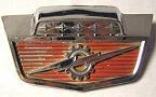
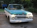
This applies to my 61 with a 3 speed column shifter. Slightly different procedures may be required for others.
To start, I acquired a switch and collar assembly from a 75 pickup.
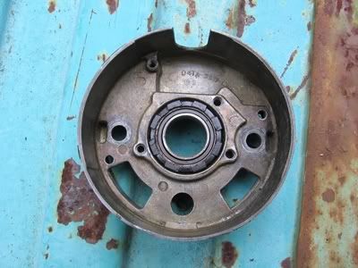
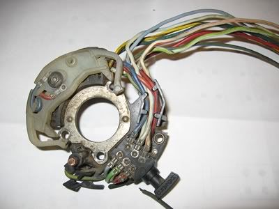
With these pieces in hand, I took the column apart to see just what I will have to do in order to mount these pieces.
To start, push down on the horn button and turn counter clockwise. This will release the horn button. You will find a spring under the button. Put these in a safe place.
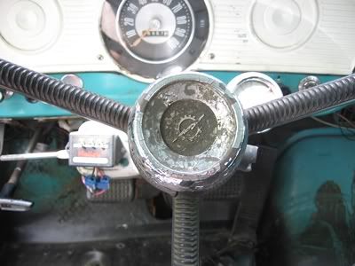
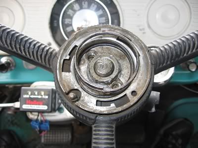
Next, loosen the steering wheel nut with a 15/16" socket but do not remove it. Unscrew it until it's about flush with the end of the shaft. Install a steering wheel puller and pull the wheel off. The nut will prevent the wheel and puller from flying off when the wheel breaks free.
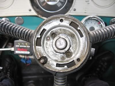
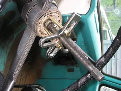
Under the steering wheel is where you will find the original switch if yours is so equipped. It appears mine was not. You will also find the horn contact which I actually broke a long time ago and so it is not in the picture. It is held on with the philips head screw which is in the picture. There will also be another spring. Once again, put these in a safe place.
Loosen the nuts at 12 and 6 o'clock to the point at which there is about 1 thread holding them on. Use the thumb and index finger of one hand to pull the nuts toward the center of the shaft. This will pull the bolt heads out of the steering column. Wiggle the collar a little while pulling with the other hand and it should come out. If it refuses to come out, try loosening the nuts a tad more.
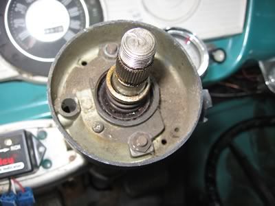
Once that is removed the shift collar will be visible. This just pulls out of the column. You may need to rotate it a little to release the linkage pieces at the bottom of the tube.
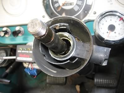
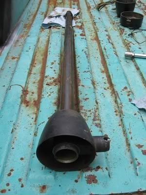
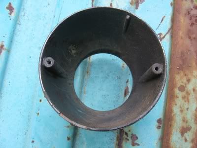
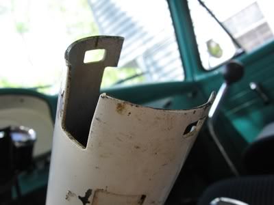
Now I'm able to see what needs to be done in order to mount the switch. This is what the top of the column tube looks like.
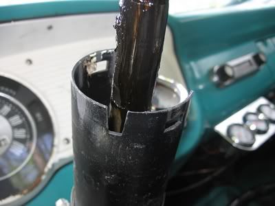
This will not work without some modification to mount the later switch. The collars are located in a different way. The original collar is located by a tab just to the left of the switch pivot. The later model collar is located by the switch pivot.
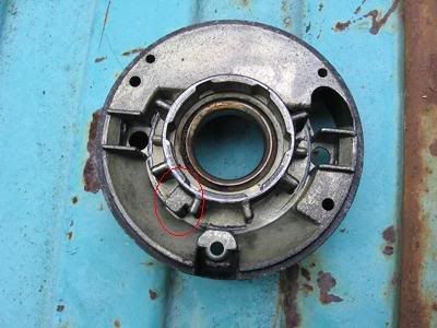
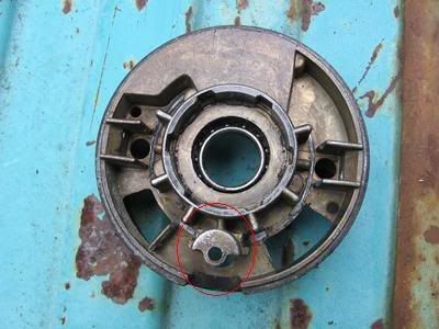
This is an easy modification to perform to the stock column. Just notch it, mount the components and you're done. However, where possible, I prefer not to modify the original parts of the truck in any way - as crazy and illogical as that sounds. I acquired a column tube from a 4 spd 1963 model. This fits the 61's steering box and has the correct notches up top for the later components.
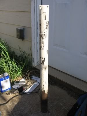
After acquiring this, I made sure the later stuff will fit.
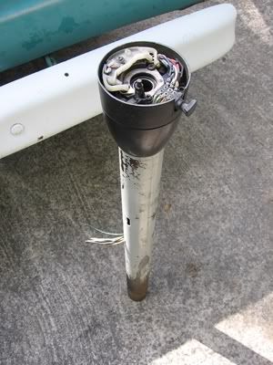
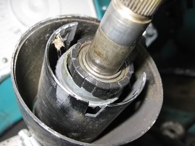
I then stripped them down to bare metal, primed and painted the parts.
Now back to the column removal. The column to dash clamp will have to be removed. I had to use a 1/2" box end wrench for this. If so equipped, shift linkage rods will need to be removed from the shift arms toward the bottom of the column. Once this was loose, I found that pulling on the column tube while twisting was easiest. I couldn't get a good angle to pry it off.
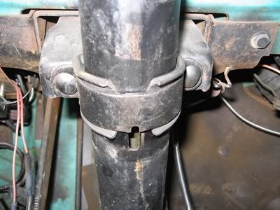
You will have to remove the sheet metal pieces which hold the column to floor seal in order to pull the shift linkage pieces through. Be ready to catch these when the tube comes off of the shaft. On the bottom of the tube will be a rubber donut. I removed it, cleaned it and installed it in the 63 tube.
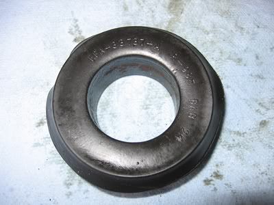
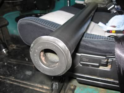
I then pushed the tube onto the steering box. I used a little grease on the box to help it slide on easier. Next, loosely install the column clamp and make sure the tab on the clamp is lining up with the oval in the column. Screw the collar pieces together.
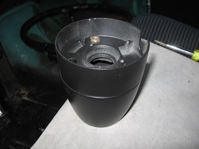
Fit the switch wires through the collar but do not yet fasten the switch. Pass the wires through the channel in the column and carefully work the collar and switch onto the column. Pull the collar nuts toward center and hold the bolts down while wiggling the assembly and minding the wires so that they don't get pinched. It might be a little tricky. Just be patient. Tighten the collar nuts, tighten the switch, install the smaller spring, mount the steering wheel and tighten the nut, install the horn button spring, and install the horn button. Now adjust the gap between the column and steering wheel to 1/16". To do this, carefully pry the column up until you have the appropriate clearance. Tighten the column clamp nuts.
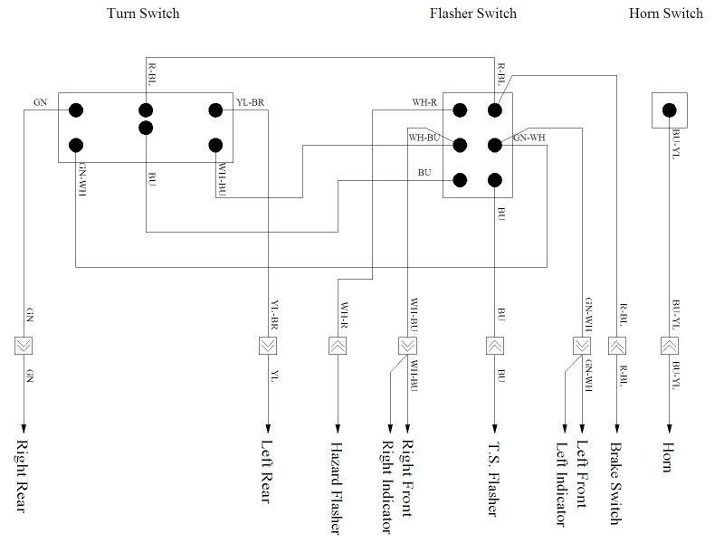
Now for the wiring.
I made this diagram once I had figured out how the switch works.
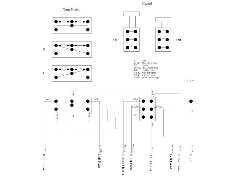
And this is how it should be wired into the 61 harness. The only thing that needs to be added is the hazard flasher.
I am not able to wire it correctly just yet. My wire harness is too messed up. So please check this against your diagram before proceeding.
And here it is almost finished. I just need to clean up the wires a little.
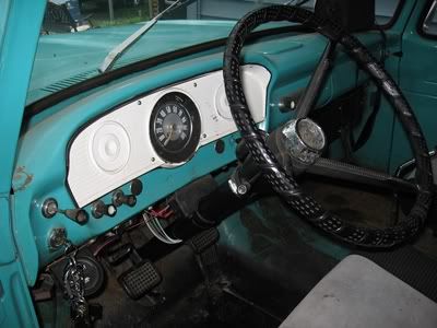
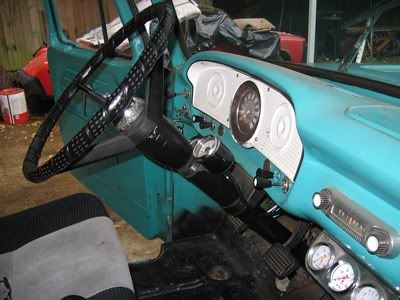
It is great to have self canceling turn signals! It looks and functions much better.