
'62 Unibody Still Plugging Along

Re: '62 Unibody
The interesting thing, that I can appreciate is…most onlookers will never know you did that to those fenderwells , and certainly won't know what you went thru mentally to come to that decision. But you did it anyway for yourself because you wanted to and it will look great.
Re: '62 Unibody
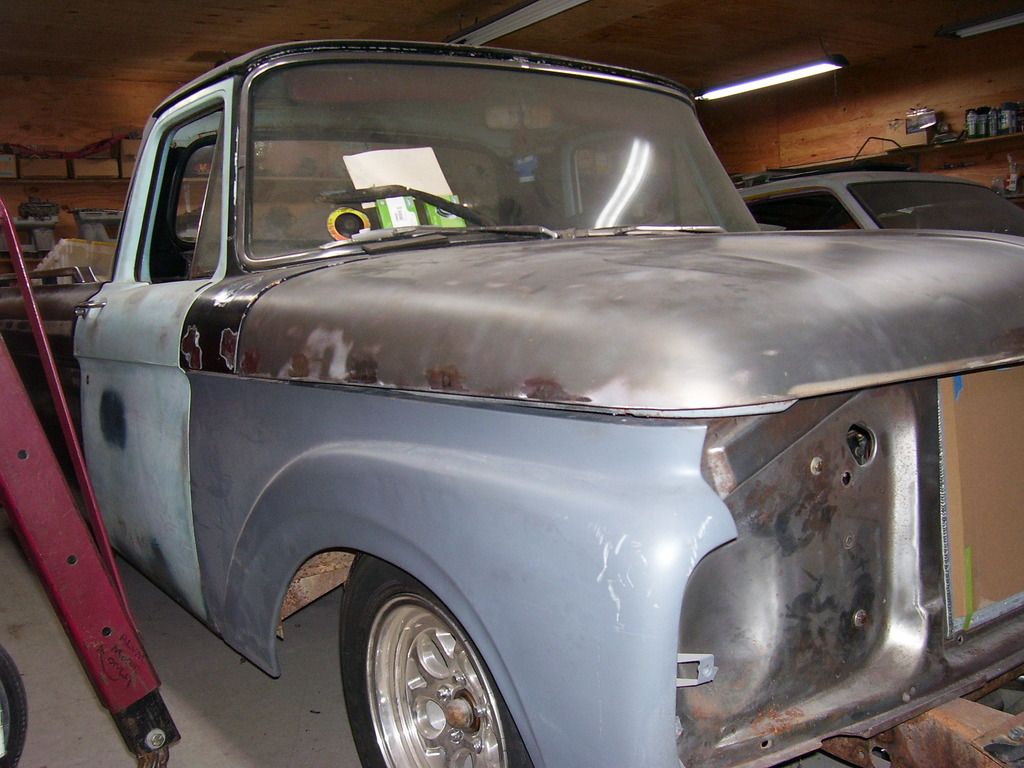
Decided to get re-acquainted with the uni this week. Cleaned up around it, checked where I was on everything.
Picked up a second set of hood hinges a few weeks ago. They have some slop in them so I figured I would rebuild them myself. Started taking them apart and getting cold feet about that process. The wear on the first rivet I took out was .0035 out of round. That let the hood mounting surface go up and down almost 1/4" of free play. These things are actually pretty tight tolerances and this little bit makes a big difference. Now I'm back to leaning towards using the reproduction hinges with some original springs on them. Talk me out of it or convince me I'm headed the right direction. Feedback please.
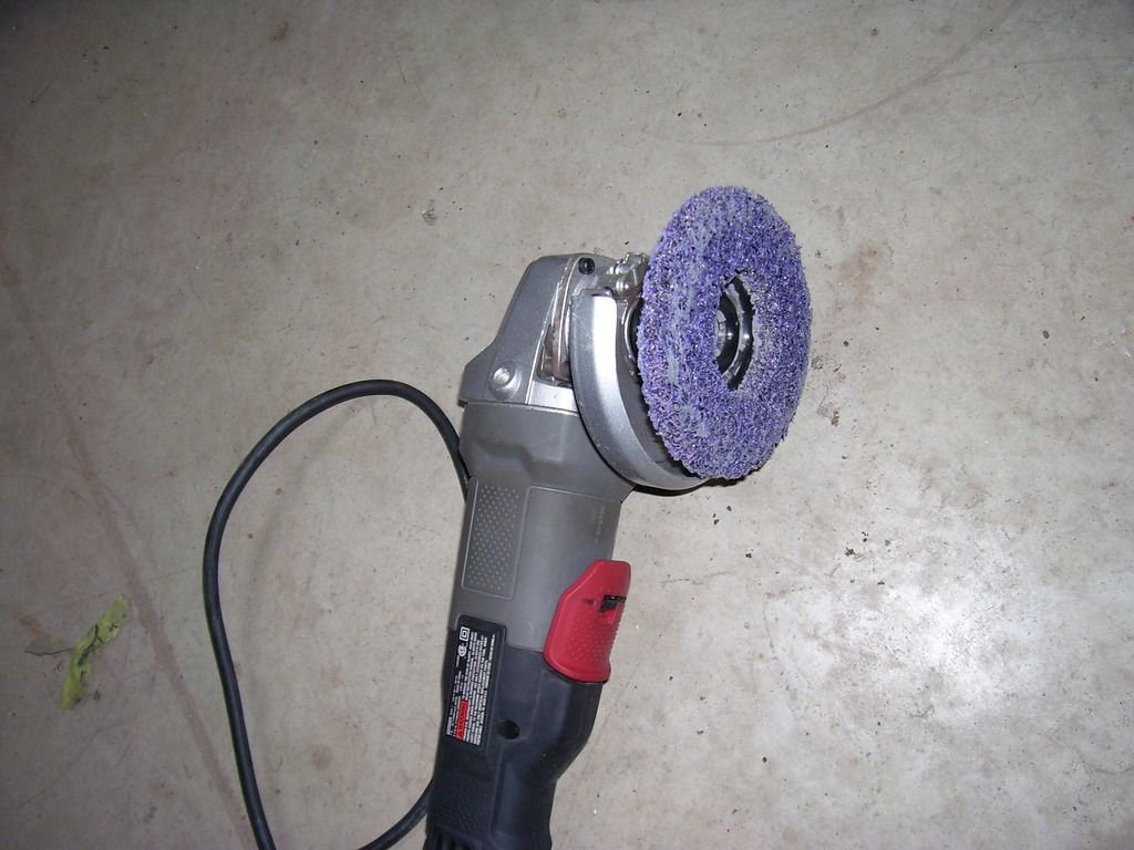
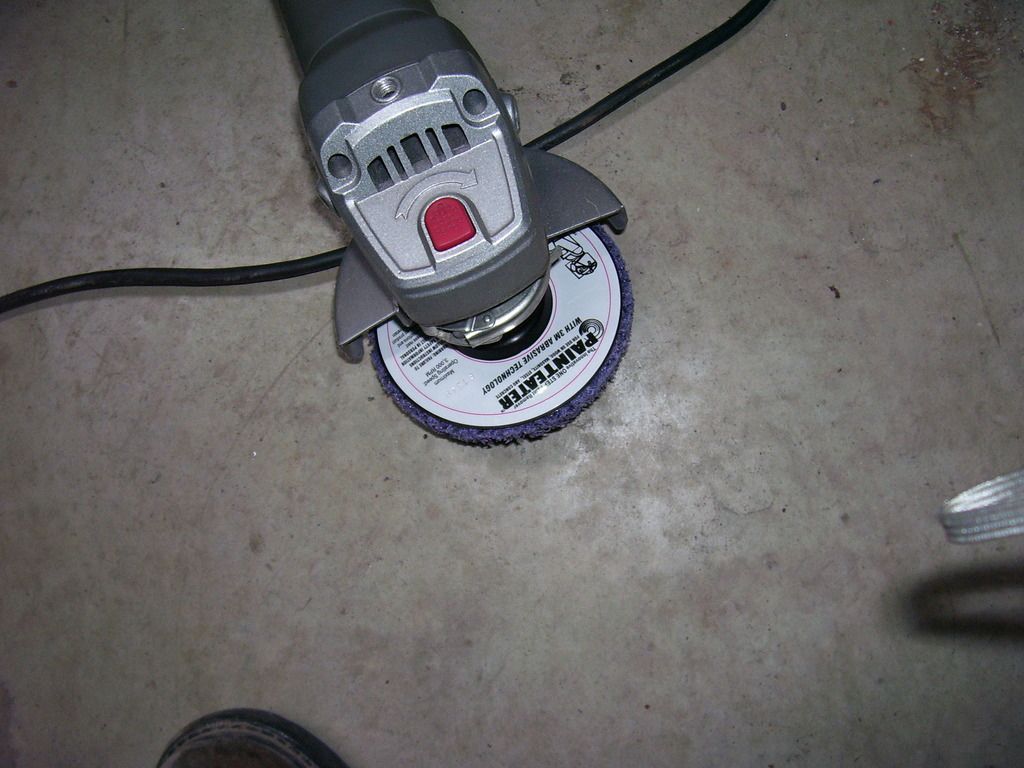
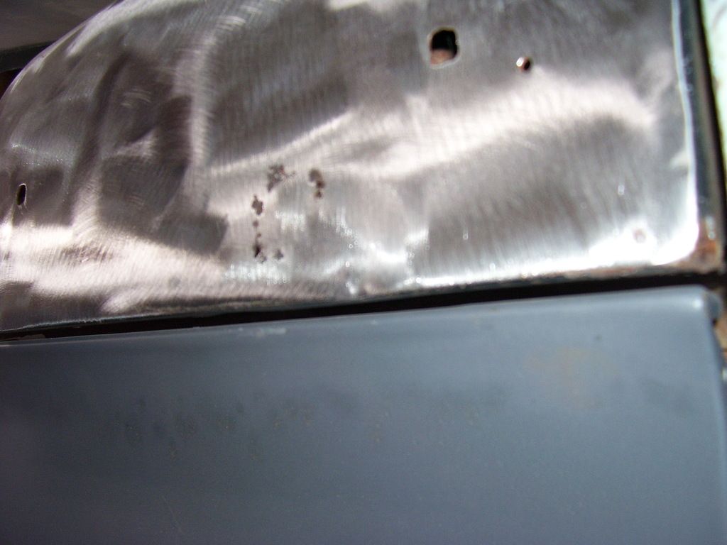
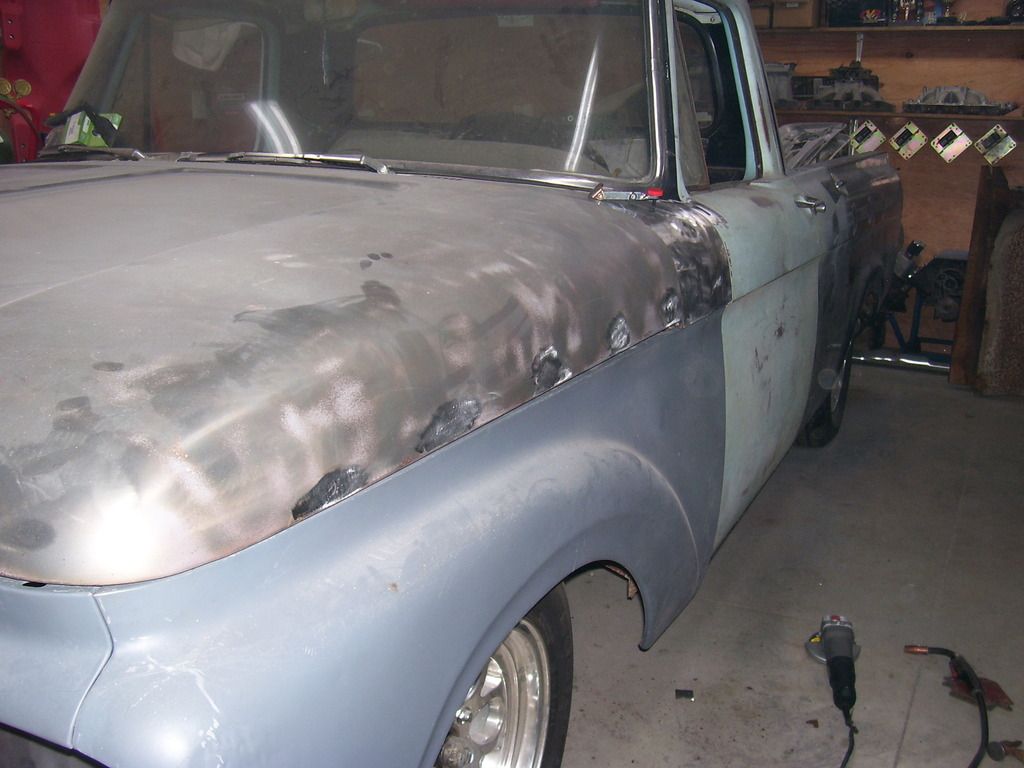
Also started doing some hole repairs on the body. My new best friend is the "Painteater". Mounts in a 4.5" grinder and this thing does eat paint. Fast. It doesn't seem to remove much metal in the process but it goes thru paint in a hurry.
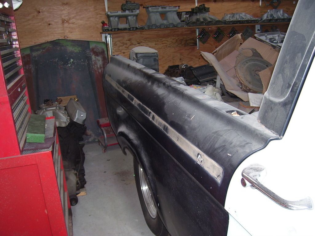
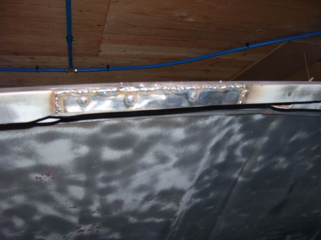
Both sides of the truck have had a series of holes drilled to mount the '66 style side trim that was on it when I got it. That left 10 - 1/4" holes to fill. The top rails also had a series of holes to mount some bed rails on top. That left a series of 8 - 3/8" holes to fill.
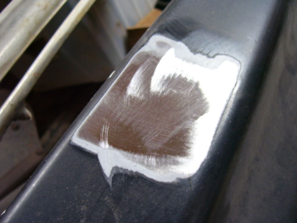
Took the Painteater to each hole and in 2 minutes had all the areas cleaned where I needed to weld. I then used a small round file to clean the insides of each hole so there was no paint or rust left to deal with when welding. You can also use the next size bigger drill bit to enlarge the holes slightly. The key to a good hole fill is working with nice clean metal all around the hole. Any paint left in the hole will bubble in your weld making a hole in your filler material and more work in the long run.
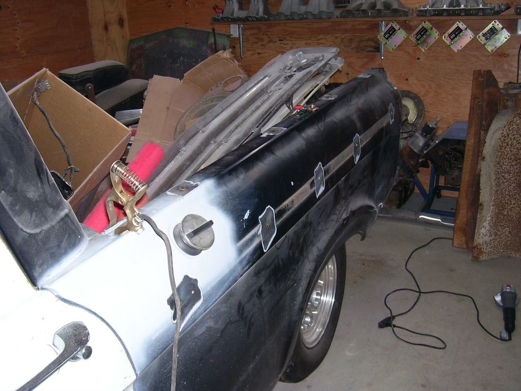
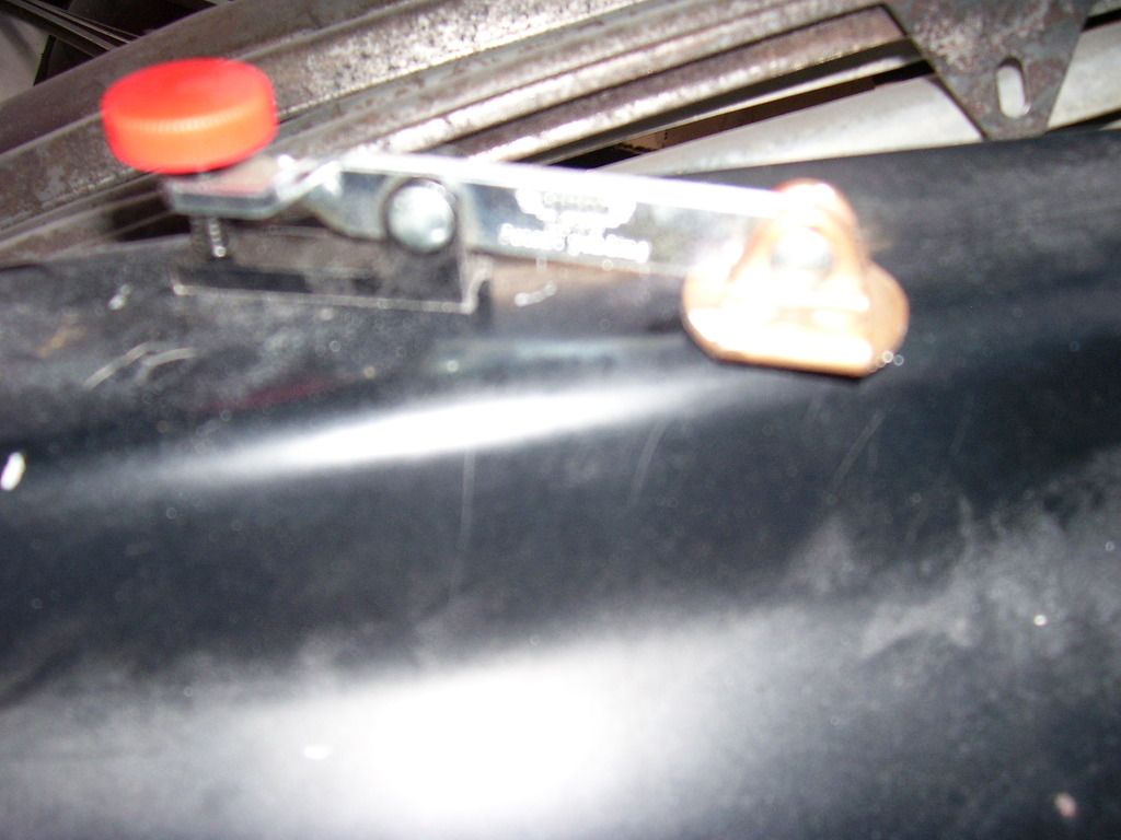
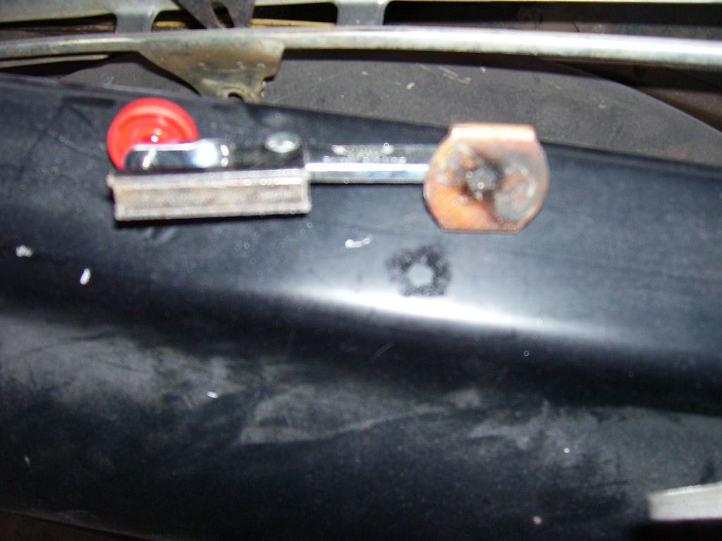
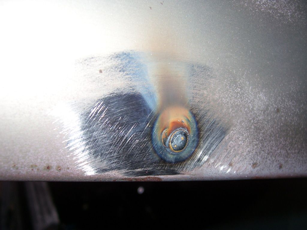
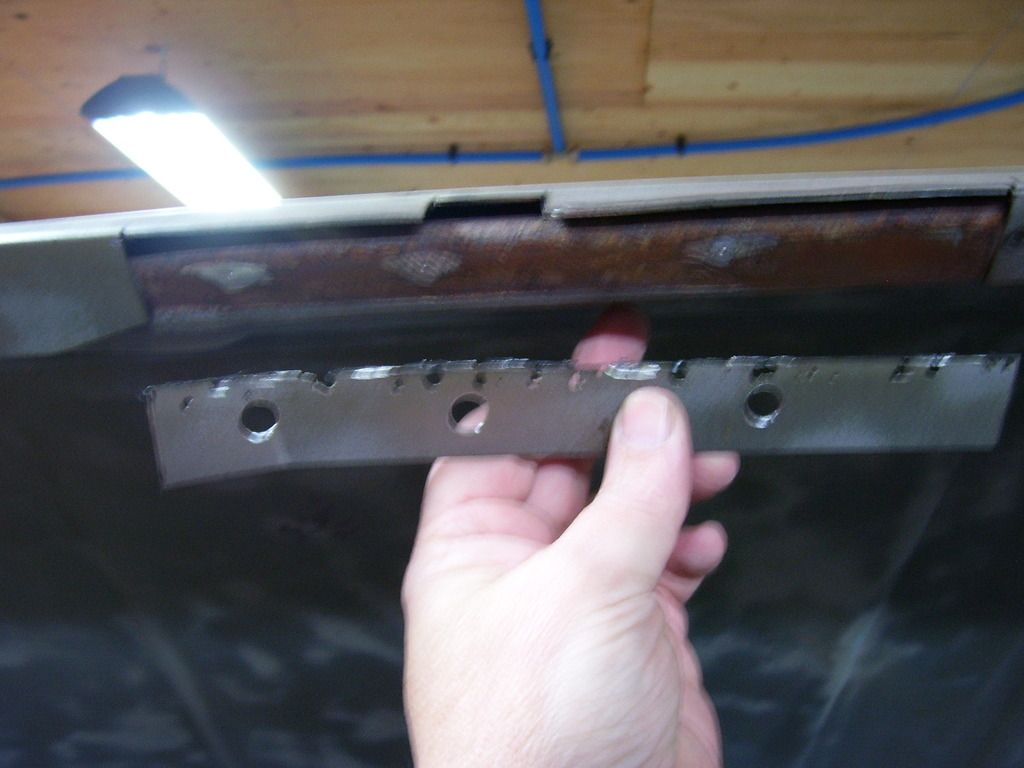
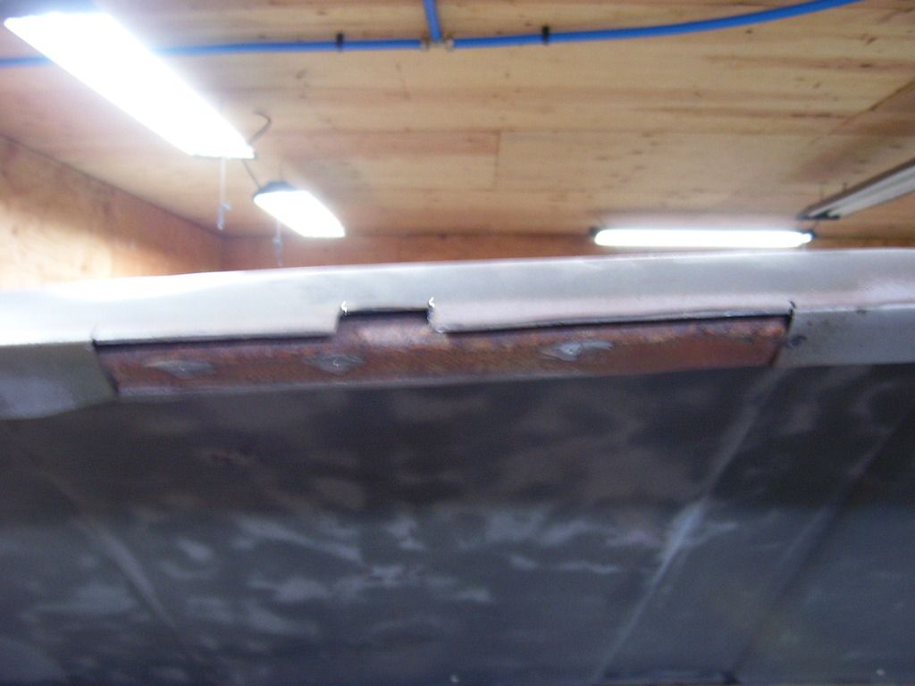
If you have ever struggled with welding a hole in on sheetmetal or thin bar steel, you need one of these. It's got a magnetic base and copper pad. You stick the base on the backside of the hole with the copper pad centered on the hole. you then turn the adjusting screw to put a slight amount of pressure on the copper pad on the back of the hole. Got mine at Eastwood and they come in a few different sizes and shapes. They are fantastic as backing on welding in patch panels, you won't believe how much easier they make things. (Sorry for the crappy pictures. Look them up on Eastwood's site. Well worth the money)
Fire up the mig and weld in the holes. Nothing special, I even had bigger wire in mine. I usually switch to something like .025 wire for sheetmetal work. It has .035 wire in it for these holes so it should have been harder than it was.
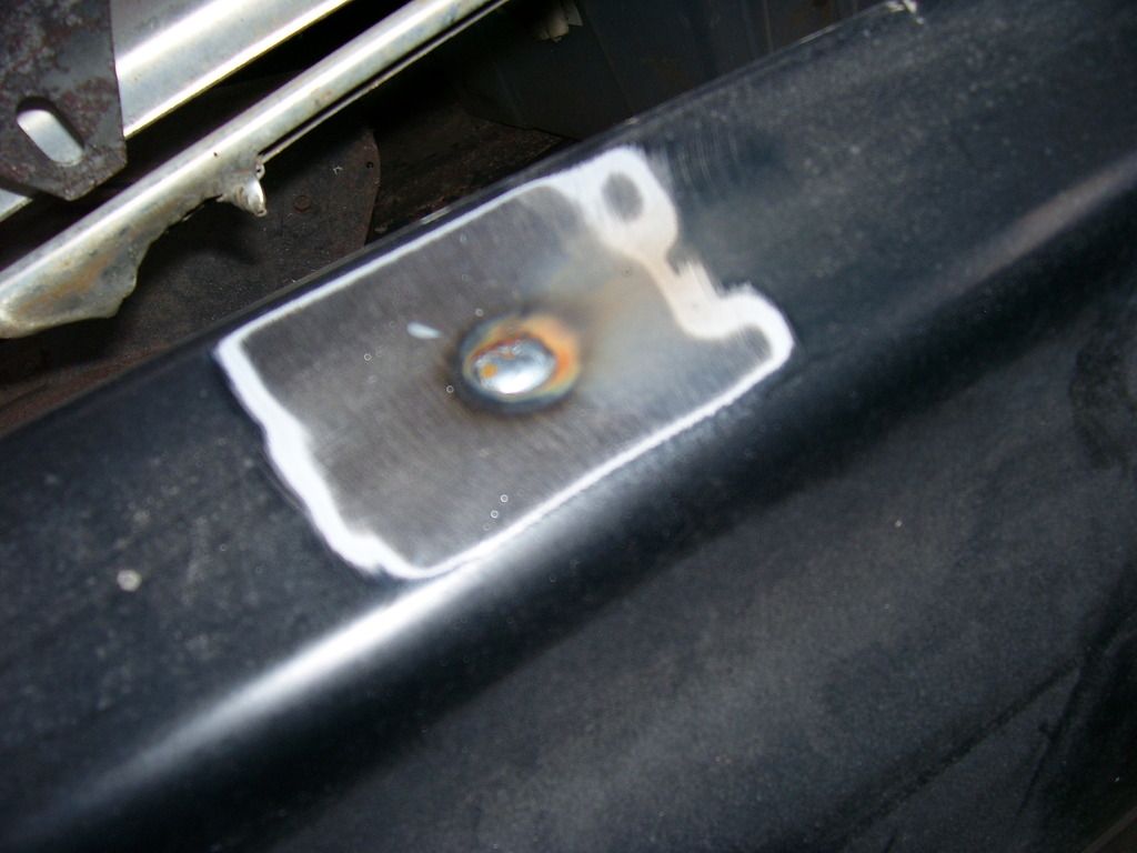
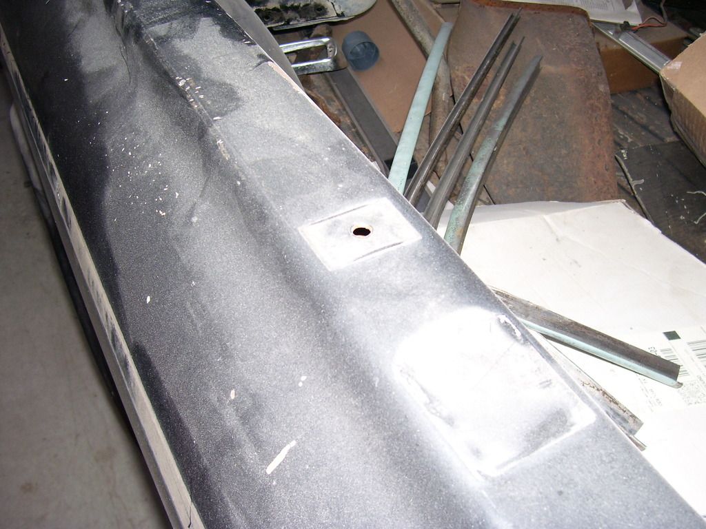
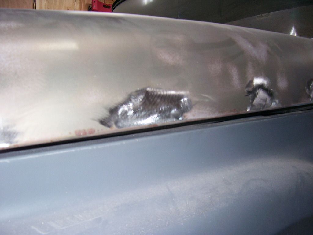
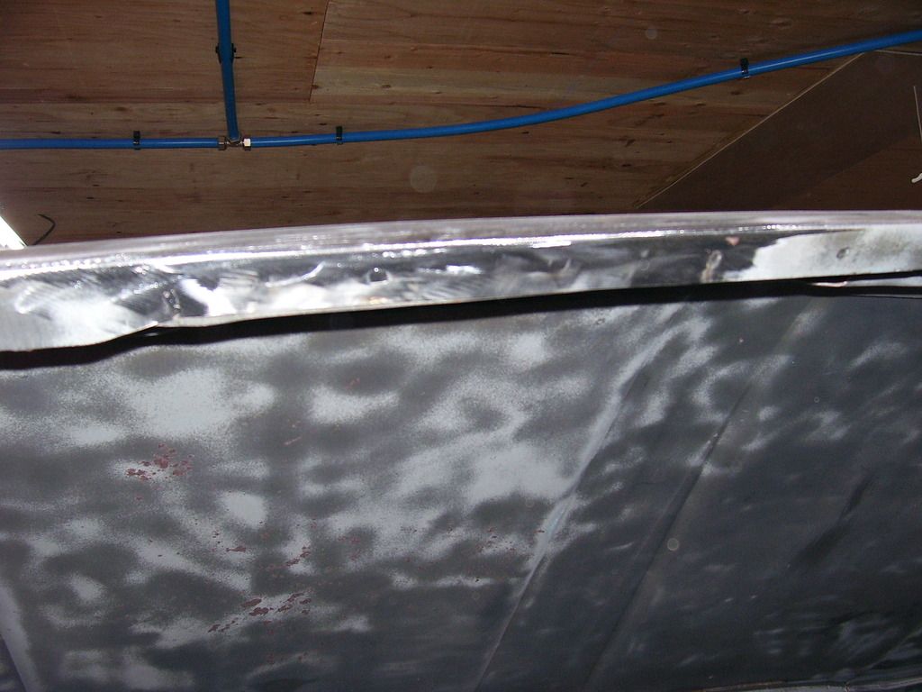
When you have it welded in, a quick pass with a flap disk on the 4.5" grinder fixes the little bit of bump you have.
Just as nice on the sides.
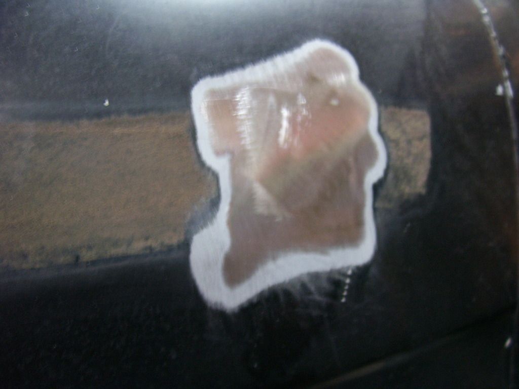
The nice thing about using the copper on the back while welding is you get complete penetration with no blow thru. The back side of the hole conforms to the copper pad so there is no mess on the backside to deal with. No mig wire where you missed or burned thru, nothing to dress up on the backside. All clean and ready for a skim of putty.
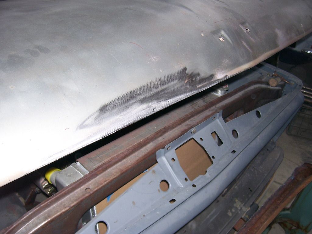
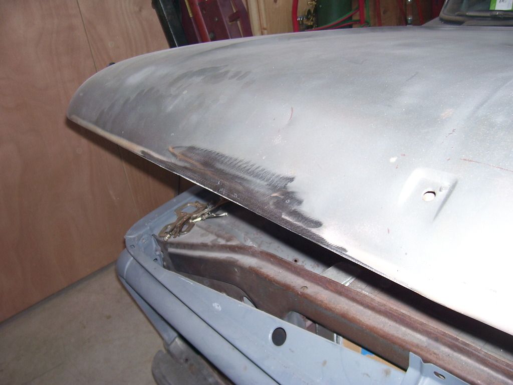
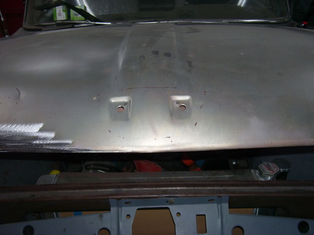
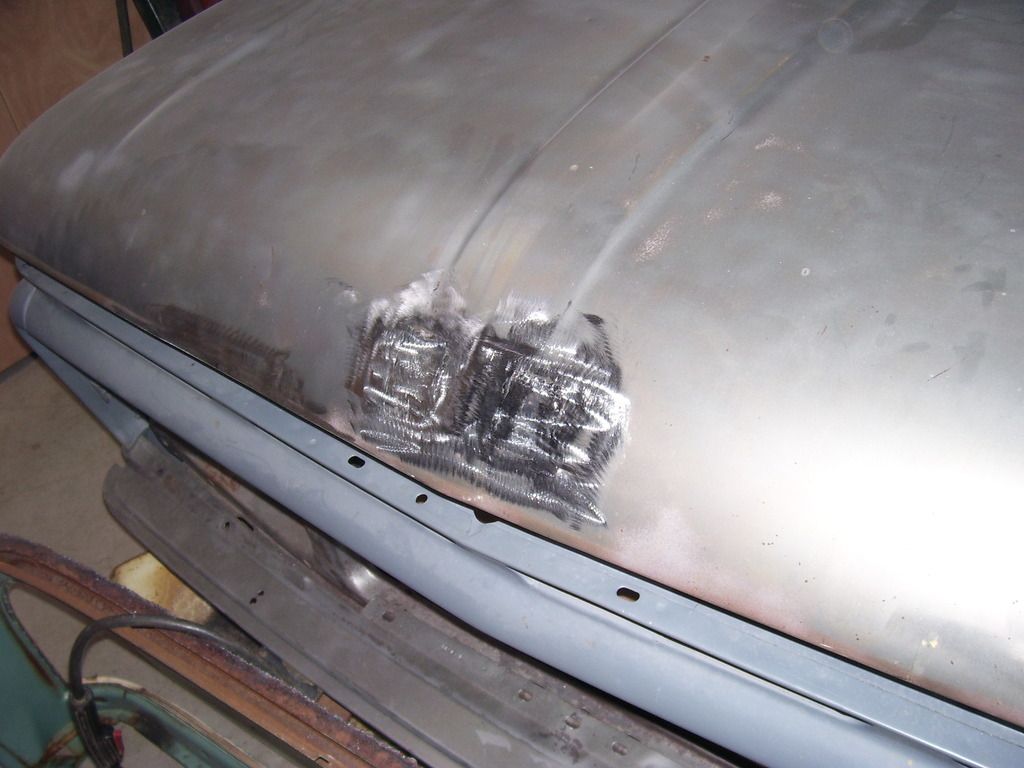
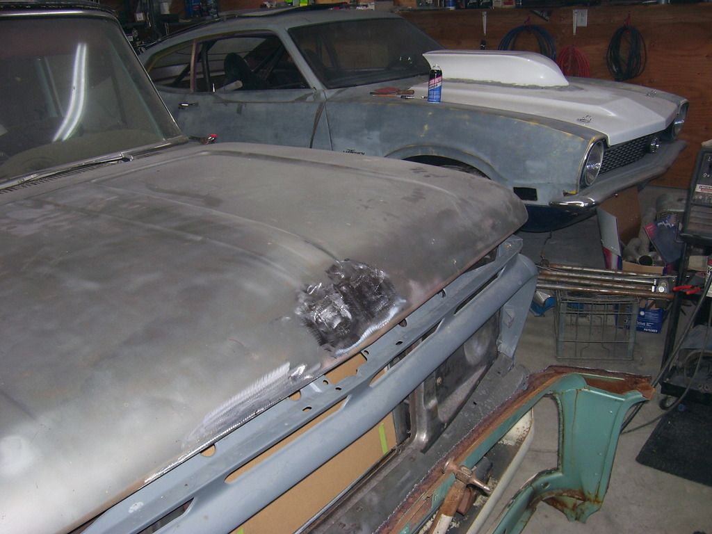
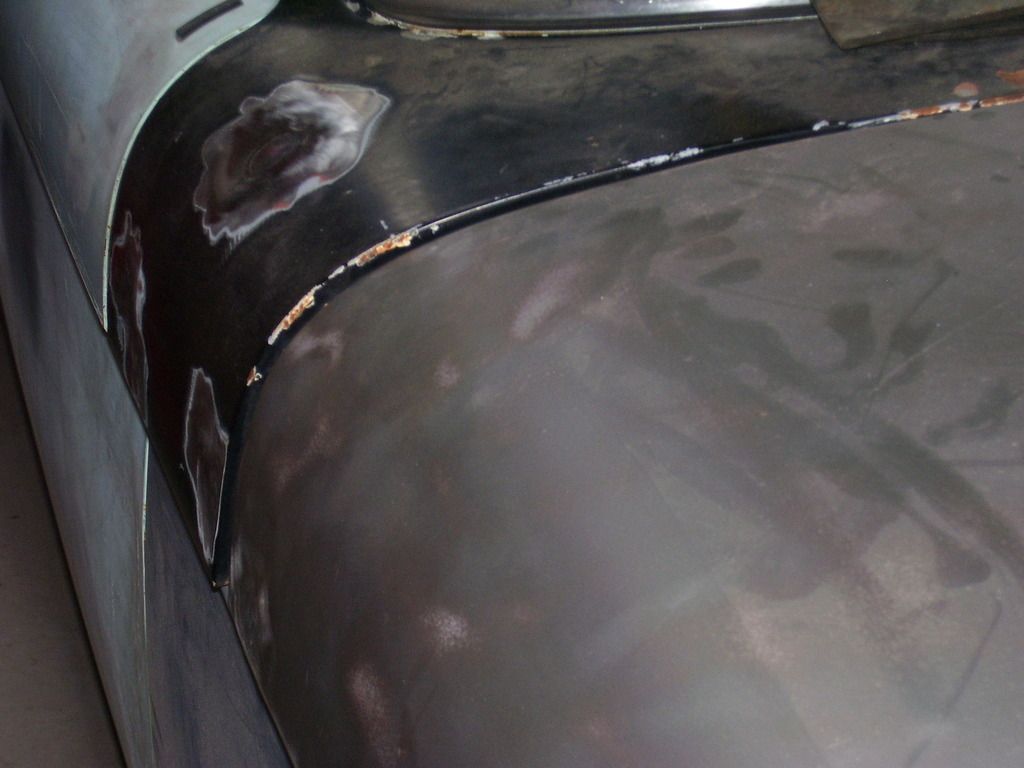
Decided to fill the holes on the hood and cowl while I was at it. Also a small rust area on the cowl (a 2" square area on the lower edge of the cowl).
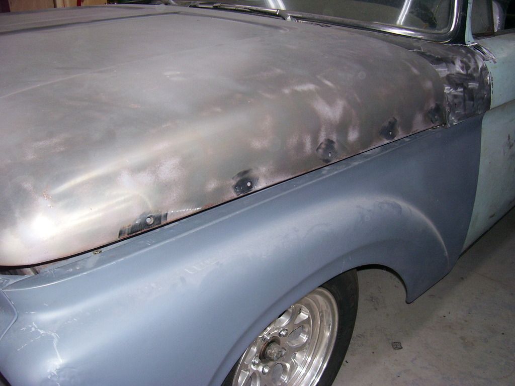
Welded in a patch and filled all the holes.
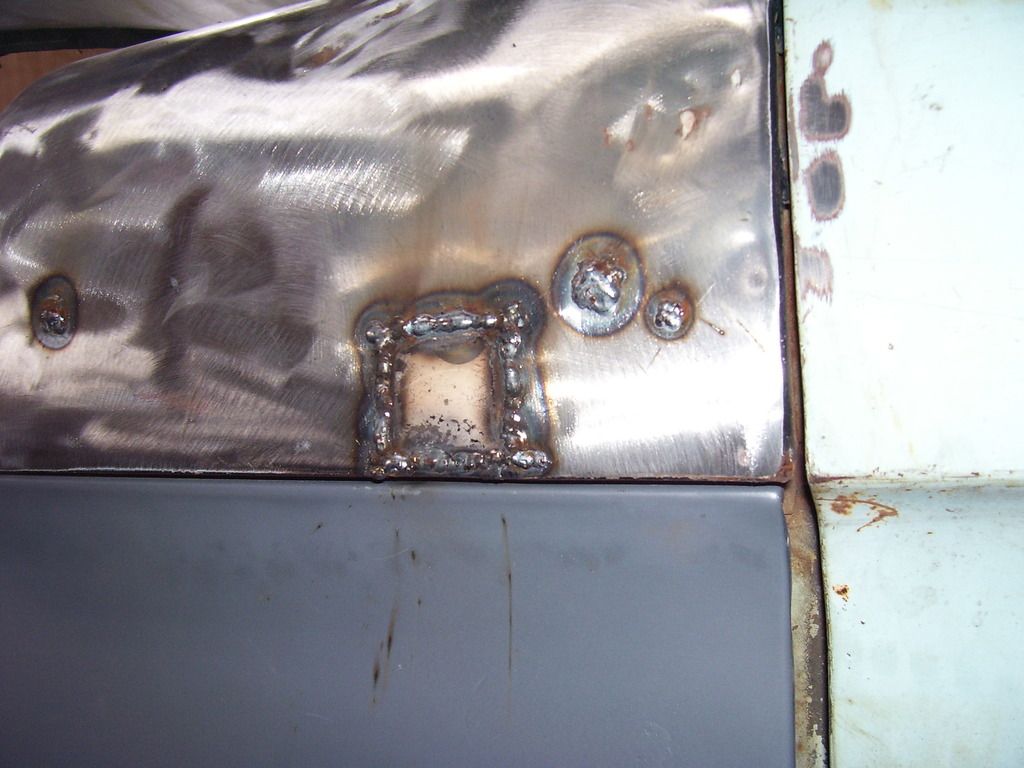
A little time with the grinder and all was well again. Still a couple small dents to pull in the cowl but the worst is fixed.
Not a big project today but I finally got motivated to get back on the truck! Been a long winter with too many distractions. Feels good to be back working on projects.
SPark
Picked up a second set of hood hinges a few weeks ago. They have some slop in them so I figured I would rebuild them myself. Started taking them apart and getting cold feet about that process. The wear on the first rivet I took out was .0035 out of round. That let the hood mounting surface go up and down almost 1/4" of free play. These things are actually pretty tight tolerances and this little bit makes a big difference. Now I'm back to leaning towards using the reproduction hinges with some original springs on them. Talk me out of it or convince me I'm headed the right direction. Feedback please.
Also started doing some hole repairs on the body. My new best friend is the "Painteater". Mounts in a 4.5" grinder and this thing does eat paint. Fast. It doesn't seem to remove much metal in the process but it goes thru paint in a hurry.


Both sides of the truck have had a series of holes drilled to mount the '66 style side trim that was on it when I got it. That left 10 - 1/4" holes to fill. The top rails also had a series of holes to mount some bed rails on top. That left a series of 8 - 3/8" holes to fill.


Took the Painteater to each hole and in 2 minutes had all the areas cleaned where I needed to weld. I then used a small round file to clean the insides of each hole so there was no paint or rust left to deal with when welding. You can also use the next size bigger drill bit to enlarge the holes slightly. The key to a good hole fill is working with nice clean metal all around the hole. Any paint left in the hole will bubble in your weld making a hole in your filler material and more work in the long run.

If you have ever struggled with welding a hole in on sheetmetal or thin bar steel, you need one of these. It's got a magnetic base and copper pad. You stick the base on the backside of the hole with the copper pad centered on the hole. you then turn the adjusting screw to put a slight amount of pressure on the copper pad on the back of the hole. Got mine at Eastwood and they come in a few different sizes and shapes. They are fantastic as backing on welding in patch panels, you won't believe how much easier they make things. (Sorry for the crappy pictures. Look them up on Eastwood's site. Well worth the money)


Fire up the mig and weld in the holes. Nothing special, I even had bigger wire in mine. I usually switch to something like .025 wire for sheetmetal work. It has .035 wire in it for these holes so it should have been harder than it was.

When you have it welded in, a quick pass with a flap disk on the 4.5" grinder fixes the little bit of bump you have.

Just as nice on the sides.

The nice thing about using the copper on the back while welding is you get complete penetration with no blow thru. The back side of the hole conforms to the copper pad so there is no mess on the backside to deal with. No mig wire where you missed or burned thru, nothing to dress up on the backside. All clean and ready for a skim of putty.
Decided to fill the holes on the hood and cowl while I was at it. Also a small rust area on the cowl (a 2" square area on the lower edge of the cowl).


Welded in a patch and filled all the holes.


A little time with the grinder and all was well again. Still a couple small dents to pull in the cowl but the worst is fixed.


Not a big project today but I finally got motivated to get back on the truck! Been a long winter with too many distractions. Feels good to be back working on projects.
SPark
1932 Ford 5 window coupe. 302/C4
1962 8V-390/C6 Unibody Short Bed Soon to be Big Window - The Lincoln that never was
2013 F150 Super Crew Eco Boost 4x4
2015 Ford Edge for the little lady, because she said so!
2007 Mustang GT, 4.6-3V/5 Speed. Only 8680 miles on the clock.
More toys, I need more toys!!!
1962 8V-390/C6 Unibody Short Bed Soon to be Big Window - The Lincoln that never was
2013 F150 Super Crew Eco Boost 4x4
2015 Ford Edge for the little lady, because she said so!
2007 Mustang GT, 4.6-3V/5 Speed. Only 8680 miles on the clock.
More toys, I need more toys!!!
-
jkimbrel65

- Posts: 965
- Joined: July 11, 2006, 8:53 pm
- Location: Athens Al

Re: '62 Unibody
I have repop hinges that I swapped the springs on and my hood fits nice
Mike
Mike
I tried being normal once...
was the worst 10 minutes of my life
was the worst 10 minutes of my life
Re: '62 Unibody
Thanks Mike. I think that is the way I'm going to go.
Appreciate it,
SPark
Appreciate it,
SPark
1932 Ford 5 window coupe. 302/C4
1962 8V-390/C6 Unibody Short Bed Soon to be Big Window - The Lincoln that never was
2013 F150 Super Crew Eco Boost 4x4
2015 Ford Edge for the little lady, because she said so!
2007 Mustang GT, 4.6-3V/5 Speed. Only 8680 miles on the clock.
More toys, I need more toys!!!
1962 8V-390/C6 Unibody Short Bed Soon to be Big Window - The Lincoln that never was
2013 F150 Super Crew Eco Boost 4x4
2015 Ford Edge for the little lady, because she said so!
2007 Mustang GT, 4.6-3V/5 Speed. Only 8680 miles on the clock.
More toys, I need more toys!!!
-
myoldman460
- Posts: 20
- Joined: August 8, 2013, 2:19 am
Re: '62 Unibody
Glad to see you are back at it. Cool project.
Re: '62 Unibody
Day 2 of holes and rust.
The hood only had 1 small area of rust after I got it media blasted. Decided that needed to go. Marked it, cut it out, drilled the spot welds holding the 2 layers together, hit it with weld thru primer, made the patch and welded it in. Not rocket science by any means.
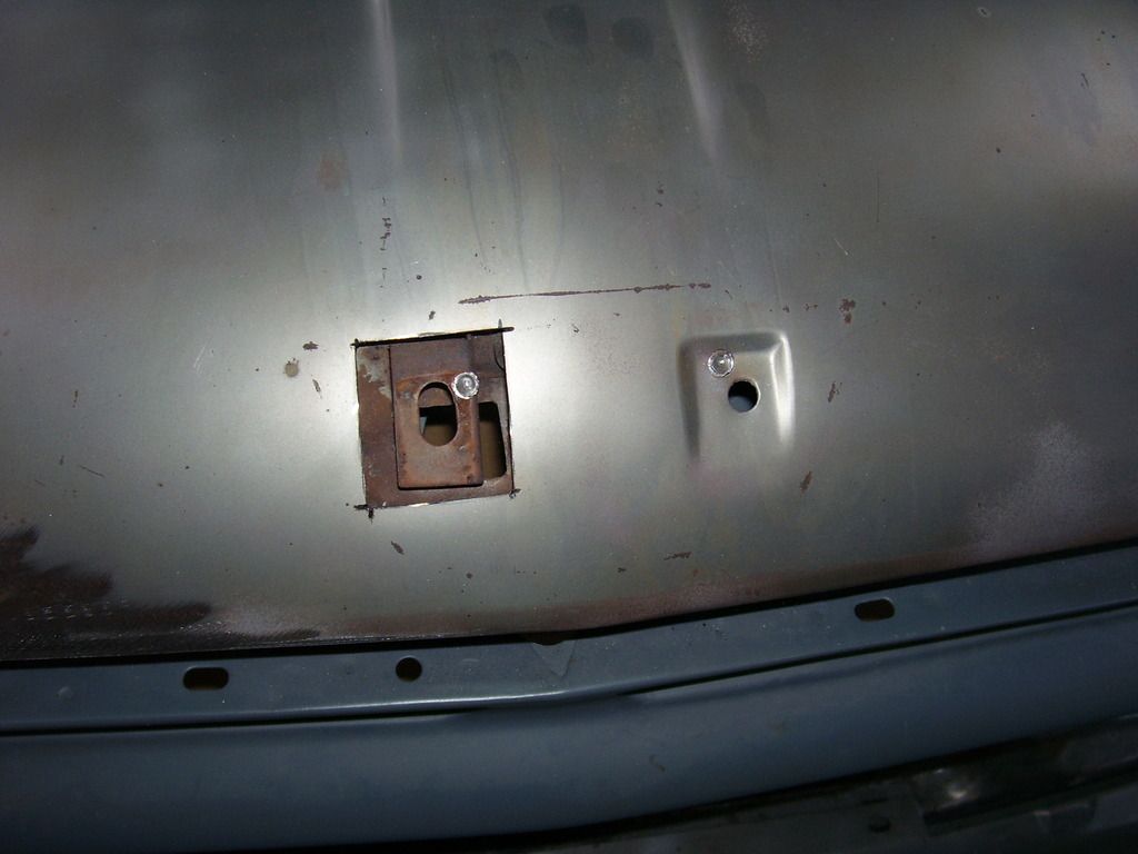
Came out pretty decent. The next piece I decided to tackle was the emblem area of the hood. You old timers know it as nosed. I cut out around the recessed emblem areas, drilled out the spot weld (that I didn't know existed here until it was blasted clean), made a patch panels and welded it in. If you do this, you might want to cut about an inch outside the emblem area and not close to it like I did. The hood dips in a little at this area and it would be easier to cut a little further out and have a better shaped area to work with. Between the peak running down the hood and the 2 recessed areas for the emblem to mount, this area gets a little funky. It worked but it took some creative hammering and prying to bring the area up a little since it's all double panel and very little direct access to the area. Lot of stress in the metal in this area from the factory.
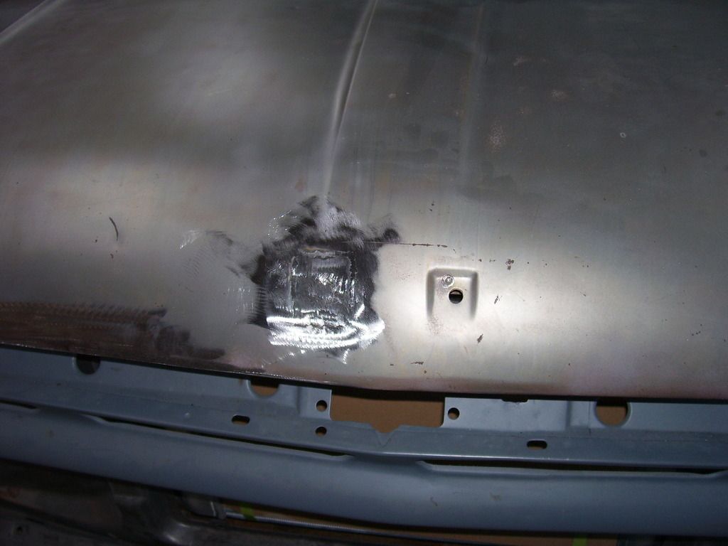
Once done, repeat with the second hole. I made these cuts about a half inch further out from the recessed area and then pried and pulled metal up to a more common crown before doing any welding. This side seemed to have a little better overall shape after grinding everything back down. With the emblem in there you can't see how the metal is sunken in around this area but it gets really obvious with the emblem gone. As a side note, I cut all my patch material out of the roof panel scrap from the unibody I got my big window section from. Figured nothing would match better than metal that come out of the same factory!
Also filled the trim holes and antenna hole on the right side today. There was a very small rust hold in the cowl on this side, too. When I cut out the metal I was surprised to find a rubber piece behind the area. It's inside the cowl where you cannot get to. It was put there from the factory as the cowl was originally welded together to stop the cowl from rattling in the area the hinge pocket/firewall/windshield base/dash all come together. No way to get to this area without cutting it out.
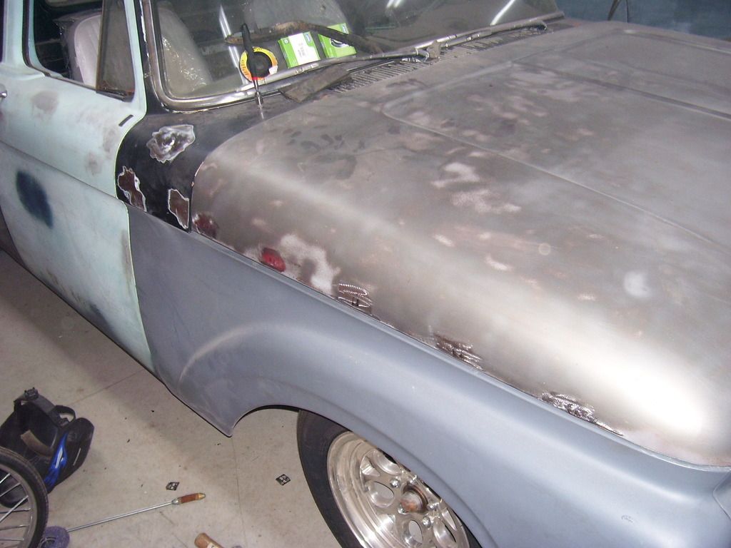
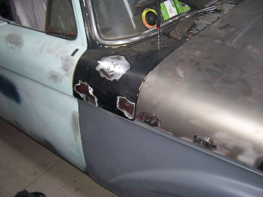
All the old trim holes have now been filled, the rust fixed in the hood and core support, the right inner fender completed and I've removed the majority of old un-needed metal from the donor section of the big window. The garage is now a dusty mess again.
SPark
The hood only had 1 small area of rust after I got it media blasted. Decided that needed to go. Marked it, cut it out, drilled the spot welds holding the 2 layers together, hit it with weld thru primer, made the patch and welded it in. Not rocket science by any means.


Came out pretty decent. The next piece I decided to tackle was the emblem area of the hood. You old timers know it as nosed. I cut out around the recessed emblem areas, drilled out the spot weld (that I didn't know existed here until it was blasted clean), made a patch panels and welded it in. If you do this, you might want to cut about an inch outside the emblem area and not close to it like I did. The hood dips in a little at this area and it would be easier to cut a little further out and have a better shaped area to work with. Between the peak running down the hood and the 2 recessed areas for the emblem to mount, this area gets a little funky. It worked but it took some creative hammering and prying to bring the area up a little since it's all double panel and very little direct access to the area. Lot of stress in the metal in this area from the factory.


Once done, repeat with the second hole. I made these cuts about a half inch further out from the recessed area and then pried and pulled metal up to a more common crown before doing any welding. This side seemed to have a little better overall shape after grinding everything back down. With the emblem in there you can't see how the metal is sunken in around this area but it gets really obvious with the emblem gone. As a side note, I cut all my patch material out of the roof panel scrap from the unibody I got my big window section from. Figured nothing would match better than metal that come out of the same factory!


Also filled the trim holes and antenna hole on the right side today. There was a very small rust hold in the cowl on this side, too. When I cut out the metal I was surprised to find a rubber piece behind the area. It's inside the cowl where you cannot get to. It was put there from the factory as the cowl was originally welded together to stop the cowl from rattling in the area the hinge pocket/firewall/windshield base/dash all come together. No way to get to this area without cutting it out.


All the old trim holes have now been filled, the rust fixed in the hood and core support, the right inner fender completed and I've removed the majority of old un-needed metal from the donor section of the big window. The garage is now a dusty mess again.
SPark
1932 Ford 5 window coupe. 302/C4
1962 8V-390/C6 Unibody Short Bed Soon to be Big Window - The Lincoln that never was
2013 F150 Super Crew Eco Boost 4x4
2015 Ford Edge for the little lady, because she said so!
2007 Mustang GT, 4.6-3V/5 Speed. Only 8680 miles on the clock.
More toys, I need more toys!!!
1962 8V-390/C6 Unibody Short Bed Soon to be Big Window - The Lincoln that never was
2013 F150 Super Crew Eco Boost 4x4
2015 Ford Edge for the little lady, because she said so!
2007 Mustang GT, 4.6-3V/5 Speed. Only 8680 miles on the clock.
More toys, I need more toys!!!
Re: '62 Unibody
Its such a shame that front hood lip was never painted inside...or at least able to drain well.
-
62bigwindow
- Posts: 408
- Joined: December 27, 2009, 6:03 pm
- Location: durham missouri
Re: '62 Unibody
Have you looked into getting your original hinges fixed? I checked on getting a set done for my '56 and was not too high. I dont know how much the repop ones cost but for mine it was $200 to get done and I would have OEM quality instead of a lower quality reproduction. Great work by the way.
Every day above ground is a good one
Re: '62 Unibody
I did check with a rebuilder. They get $400 a pair for this style hinge. Several moving parts need rebuilt and the rivets for the hinges are custom made one at a time. There are no available parts that will work other than custom made. They also only do original style rebuilds. I asked about non-stock appearing rivets and they won't do it. They are the most expensive hinges they rebuild because of this.
Ordered a set of replacement hinges late last week. Should have them soon!
SPark
Ordered a set of replacement hinges late last week. Should have them soon!
SPark
1932 Ford 5 window coupe. 302/C4
1962 8V-390/C6 Unibody Short Bed Soon to be Big Window - The Lincoln that never was
2013 F150 Super Crew Eco Boost 4x4
2015 Ford Edge for the little lady, because she said so!
2007 Mustang GT, 4.6-3V/5 Speed. Only 8680 miles on the clock.
More toys, I need more toys!!!
1962 8V-390/C6 Unibody Short Bed Soon to be Big Window - The Lincoln that never was
2013 F150 Super Crew Eco Boost 4x4
2015 Ford Edge for the little lady, because she said so!
2007 Mustang GT, 4.6-3V/5 Speed. Only 8680 miles on the clock.
More toys, I need more toys!!!
Re: '62 Unibody
Sorry no pics for this step, just couldn't get any that really showed anything.
After getting all the holes filled and rust repaired in the cowl, I still had 3 big dents to deal with. Something had obviously been hit against the cowl on the left side since it's last paint job. The 3 dents (2 side by side and 1 just below) were all roughly 2" in diameter and anywhere from 1/2" deep for the shallow one to almost 1-1/4" deep for the big one, with surrounding body depressed slightly. There was also a deep crease in one small area of the biggest hole that was probably 1/8" deeper than the deepest dent. All were on the high point of the crown of the cowl. I didn't want to cut these 3 areas out and I sure didn't want to use 1-1/4" of mud when the time came. No access to the back side of the panel in any way I could figure out where I could get a hammer in to do anything about it. It's just below the windshield and working down towards the beltline.
The solution? Stud welding gun. You own one? Mt neither...but now I do. While on a little trip yesterday, I swung past Harbor Freight and bought a cheapo stud welding gun kit for $99.99.
http://www.harborfreight.com/stud-welde ... 98357.html
Comes with a 40 amp gun, 2mm and 3mm studs, 2mm and 3mm tips and a slide hammer. Really simple. In about 25 minutes I had pulled all 3 dents. Took about 15 pins, 2 rounds of welding/hammering/pulling and cutting off those studs to get new ones where they were needed. The slide hammer that comes with these is universally bitched about in reviews but I had absolutely no problems while using the 3mm studs. Haven't tried it with the 2mm studs yet. My guess is people don't fully understand how the clamping method of the slide hammer works with this style attachment point. Very simple and easy, didn't have a single problem after playing with a stud in the puller on the bench before tackling the truck. The trick to removing dents is work in a spiral pattern from outside towards the deepest part of the dent. Don't start at the deep spot, make gradual pulls and sneak up on the deep spot. If you try to pull the deepest spot first, you will only stretch the metal and make a new mess. Patience. Patience. (Something I do not possess an abundance of).
Now, the entire area is nearly back to normal profile. The deepest spot needing mud is now 3/16" and it's a small crease that is 1" long. I just can't get that area any further out without stretching the areas around it and making more work. Everything else is 1/8" mud or less when this area gets finished. Very happy with the results.
Highly recommend the stud welding gun from Harbor Freight. Worked great, couldn't have asked for any more from it. It may not last forever but as far as I'm concerned, it's already paid for itself.
SPark
1932 Ford 5 window coupe. 302/C4
1962 8V-390/C6 Unibody Short Bed Soon to be Big Window - The Lincoln that never was
2013 F150 Super Crew Eco Boost 4x4
2015 Ford Edge for the little lady, because she said so!
2007 Mustang GT, 4.6-3V/5 Speed. Only 8680 miles on the clock.
More toys, I need more toys!!!
1962 8V-390/C6 Unibody Short Bed Soon to be Big Window - The Lincoln that never was
2013 F150 Super Crew Eco Boost 4x4
2015 Ford Edge for the little lady, because she said so!
2007 Mustang GT, 4.6-3V/5 Speed. Only 8680 miles on the clock.
More toys, I need more toys!!!
-
myoldman460
- Posts: 20
- Joined: August 8, 2013, 2:19 am
Re: '62 Unibody
Look to The Eastwood Company for a tool called the "shoot suit". Its used with your dent puller.
Re: '62 Unibody
I've considered one of those. I think it would help where I have the deep crease left. Everything else came out very easily and has nice shape.
SPark
SPark
1932 Ford 5 window coupe. 302/C4
1962 8V-390/C6 Unibody Short Bed Soon to be Big Window - The Lincoln that never was
2013 F150 Super Crew Eco Boost 4x4
2015 Ford Edge for the little lady, because she said so!
2007 Mustang GT, 4.6-3V/5 Speed. Only 8680 miles on the clock.
More toys, I need more toys!!!
1962 8V-390/C6 Unibody Short Bed Soon to be Big Window - The Lincoln that never was
2013 F150 Super Crew Eco Boost 4x4
2015 Ford Edge for the little lady, because she said so!
2007 Mustang GT, 4.6-3V/5 Speed. Only 8680 miles on the clock.
More toys, I need more toys!!!
Re: '62 Unibody
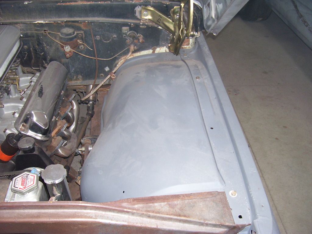
Well, those that know me, know I can't settle for "close enough". Drives me crazy to look at something I've made and think I could have done it better. If you've followed along, you know I've gone both ways with my right inner fender. No more. Today I pulled it back off, dug out my big truck/4x4 inner and another stock inner. Spent another hour looking, measuring, comparing crowns in curves, etc. GOTTA DO IT!
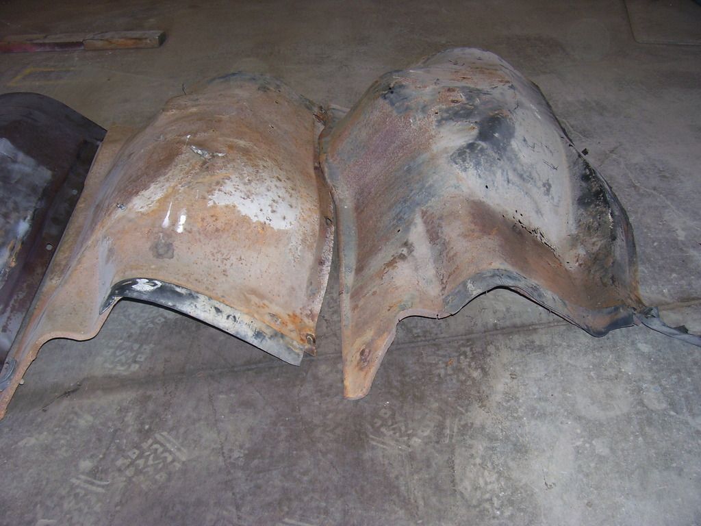
This is a stock inner front and back. Notice the dip we are all familiar with below the battery tray area. Also notice the front dips in beside the radiator area.
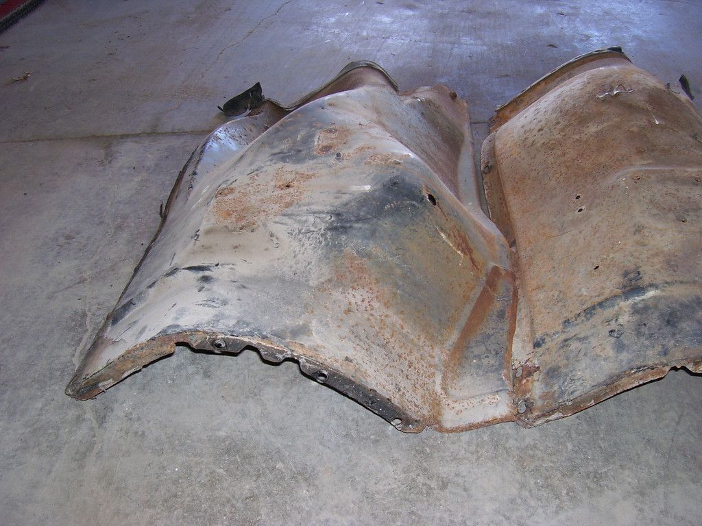
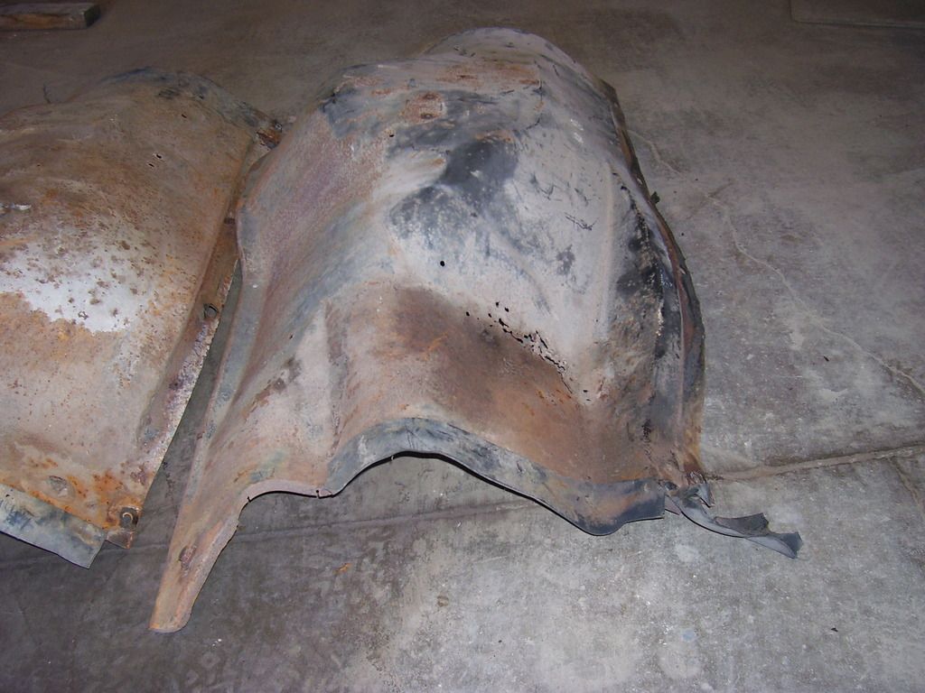
This is a stock big truck/4x4 inner front and back. Notice there is no dip below where the battery should be. Big trucks put the battery elsewhere so it isn't needed. Also notice it is straight from front to back along the bottom edge without any dip in at the front.
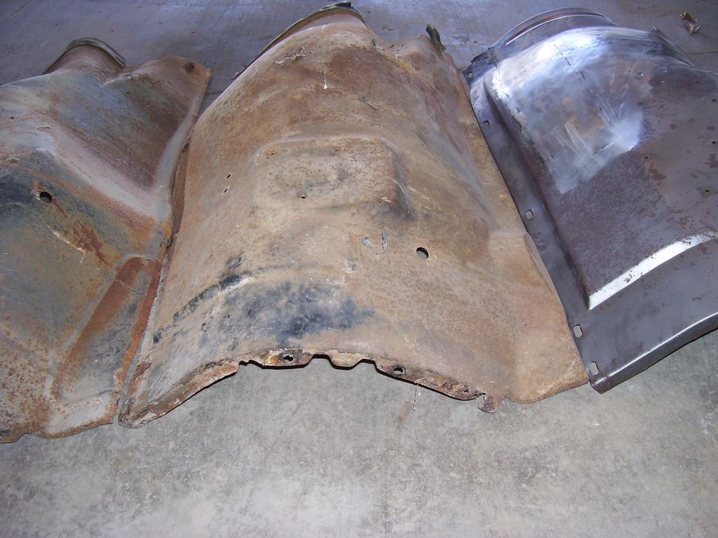
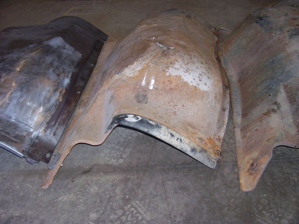
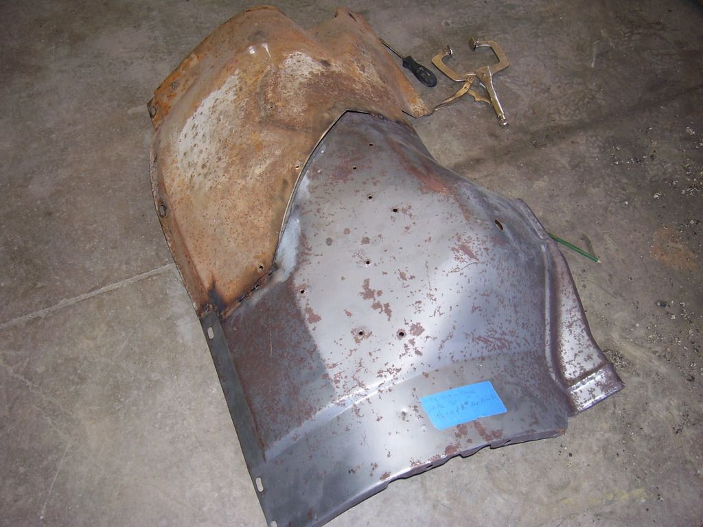
This is the one I made, front and back. Combining all the things I liked about the 2. Problem is, the crown in the piece I made is too flat and doesn't actually match the left side like it should.
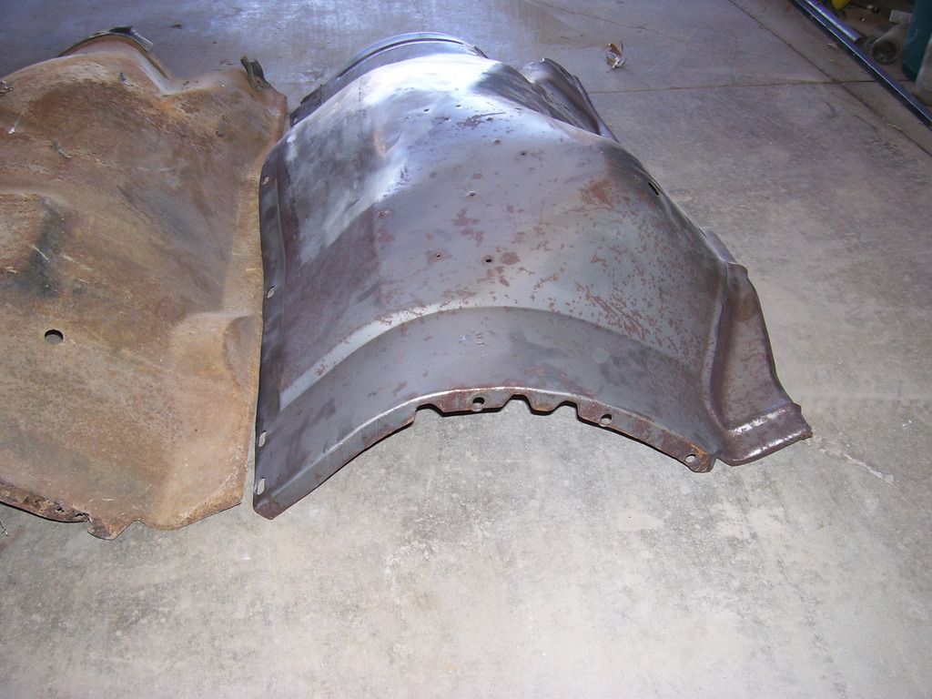
Comparing the stocker with the big truck pieces, you can see the differences. Front and back.
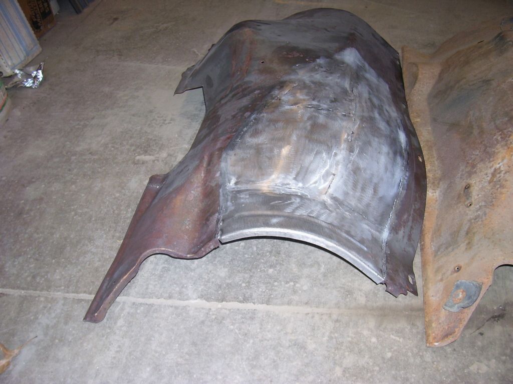
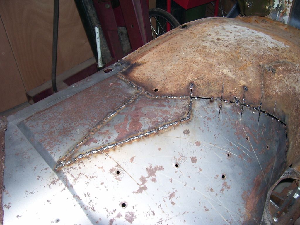
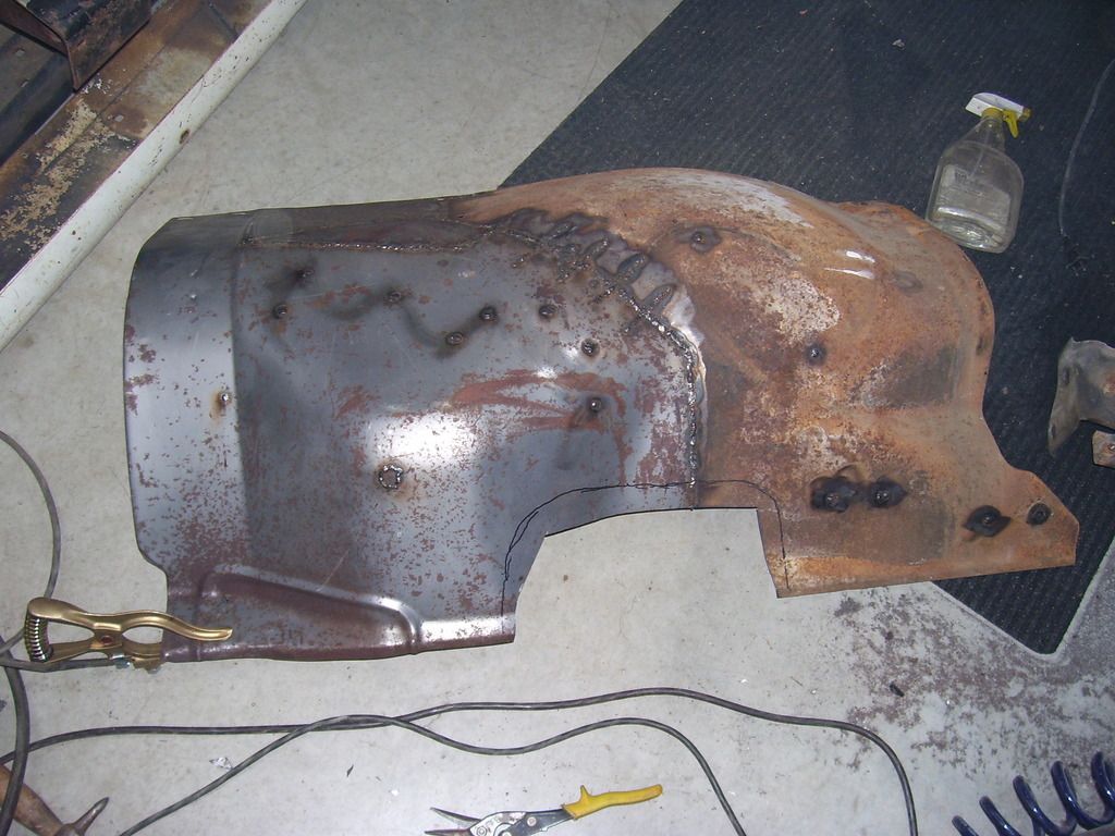
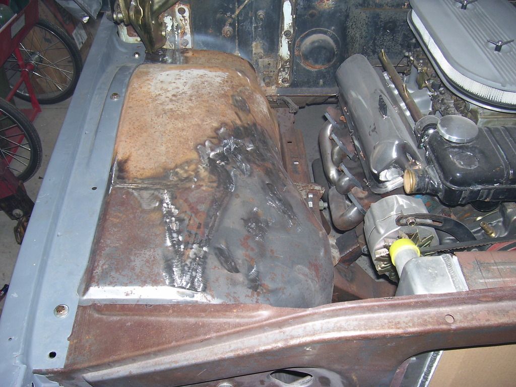
Decided to hack stuff up. Cut the rear portion out of the big truck inner, clamped it over the top of the one I had built and marked some rough cut lines. The areas I used for control were the top edge that sits under the fender (it has to be straight front to back and center to center of holes has to remain) and the overall length of the bottom edge. Almost an hour trimming, measuring. staring at it, trimming some more, checking edge alignment and I was ready to tack it together.
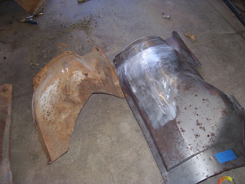
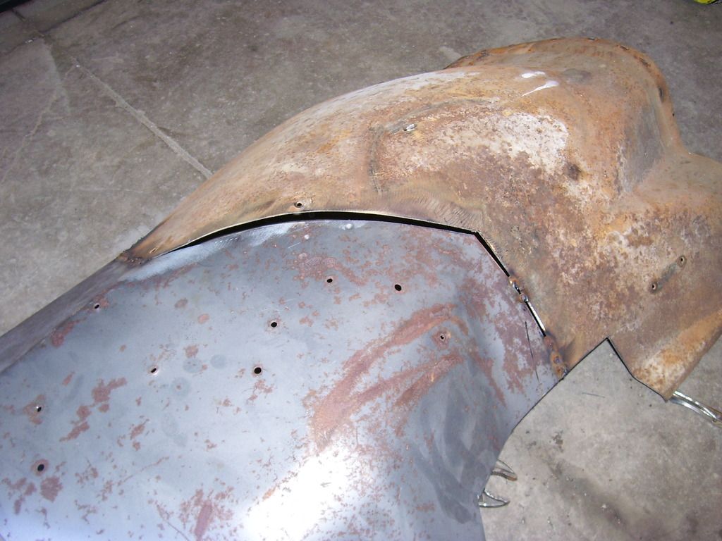
You can see some of the crowned areas don't match. I spent a bit of time cutting relief slots, hammer and dolly working the areas to match and tacking it all back together. Once it was solid enough, it was time for a test fit back on the truck with the fender and radiator support. Let's see if we wasted 4 hours today. Drumroll please.
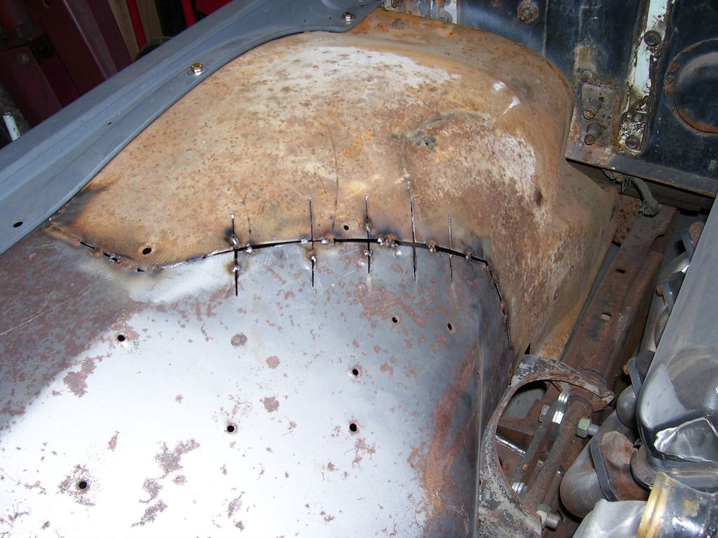
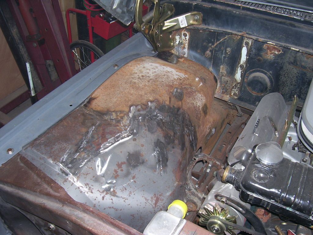
That is a keeper! I still need to remove the flat voltage regulator mounting pad area and fill a few holes, make a small rust repair and trim the upper control arm area a bit more. Another hour or so of welding, some more work with the hammers and a lot of grinding and I think we have the best answer for achieving what I wanted to. Now both sides will be mirror images of each other. I really don't recommend this modification to anyone. A lot of work just so something "looks right" to me. I tend to fixate on things like this and just can't leave well enough alone. It will look good (I hope) when done but 99% of the world will have no idea something has even been done.
Got my hood hinges from Carolina Classics. Made in Argentina. Springs are strong enough at this point to hold the hood fully open, we'll see how they work after holding that hood for a while. I have a set of stock springs bead blasted, painted and ready to go on if needed. I have both hinges moved all the way up and my hood still sits almost 5/8" low on the cowl. So low I cannot close the hood because it hits the fender tops at the back. Either going to have to make some 3/4" shims to fit between the hood and hinge or slot holes some more or both. The front to back adjustment has plenty of adjustment but up and down is a mess.
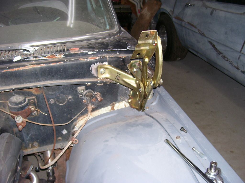
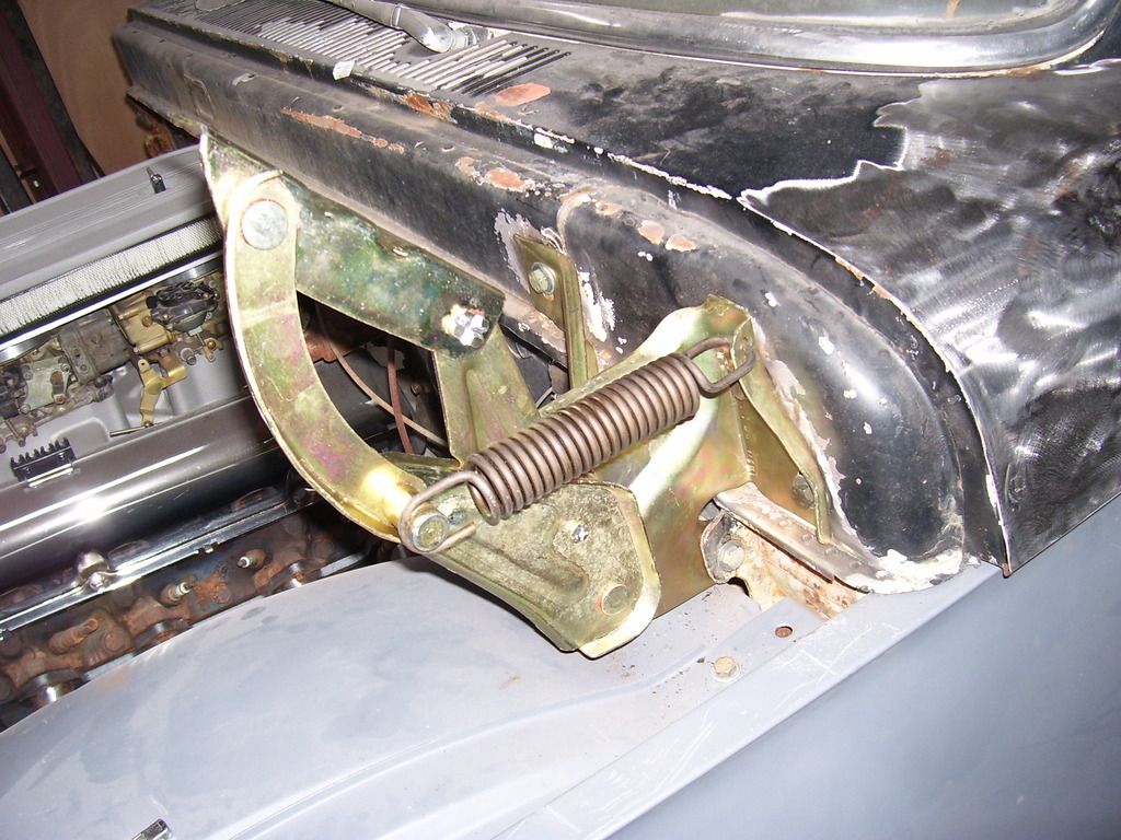
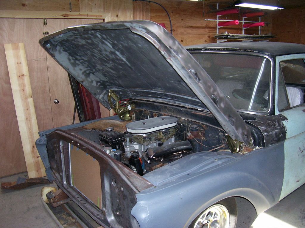
These pics are with the hinges all the way up, maxed out and a couple 1/2" flat washers between the hinge and hood on the right side.
That's all for today. I suggest getting help for working with the hood, those things are heavy and I'm about wiped out wrestling with it.
SPark
This is a stock inner front and back. Notice the dip we are all familiar with below the battery tray area. Also notice the front dips in beside the radiator area.


This is a stock big truck/4x4 inner front and back. Notice there is no dip below where the battery should be. Big trucks put the battery elsewhere so it isn't needed. Also notice it is straight from front to back along the bottom edge without any dip in at the front.


This is the one I made, front and back. Combining all the things I liked about the 2. Problem is, the crown in the piece I made is too flat and doesn't actually match the left side like it should.


Comparing the stocker with the big truck pieces, you can see the differences. Front and back.


Decided to hack stuff up. Cut the rear portion out of the big truck inner, clamped it over the top of the one I had built and marked some rough cut lines. The areas I used for control were the top edge that sits under the fender (it has to be straight front to back and center to center of holes has to remain) and the overall length of the bottom edge. Almost an hour trimming, measuring. staring at it, trimming some more, checking edge alignment and I was ready to tack it together.


You can see some of the crowned areas don't match. I spent a bit of time cutting relief slots, hammer and dolly working the areas to match and tacking it all back together. Once it was solid enough, it was time for a test fit back on the truck with the fender and radiator support. Let's see if we wasted 4 hours today. Drumroll please.


That is a keeper! I still need to remove the flat voltage regulator mounting pad area and fill a few holes, make a small rust repair and trim the upper control arm area a bit more. Another hour or so of welding, some more work with the hammers and a lot of grinding and I think we have the best answer for achieving what I wanted to. Now both sides will be mirror images of each other. I really don't recommend this modification to anyone. A lot of work just so something "looks right" to me. I tend to fixate on things like this and just can't leave well enough alone. It will look good (I hope) when done but 99% of the world will have no idea something has even been done.
Got my hood hinges from Carolina Classics. Made in Argentina. Springs are strong enough at this point to hold the hood fully open, we'll see how they work after holding that hood for a while. I have a set of stock springs bead blasted, painted and ready to go on if needed. I have both hinges moved all the way up and my hood still sits almost 5/8" low on the cowl. So low I cannot close the hood because it hits the fender tops at the back. Either going to have to make some 3/4" shims to fit between the hood and hinge or slot holes some more or both. The front to back adjustment has plenty of adjustment but up and down is a mess.


These pics are with the hinges all the way up, maxed out and a couple 1/2" flat washers between the hinge and hood on the right side.


That's all for today. I suggest getting help for working with the hood, those things are heavy and I'm about wiped out wrestling with it.
SPark
1932 Ford 5 window coupe. 302/C4
1962 8V-390/C6 Unibody Short Bed Soon to be Big Window - The Lincoln that never was
2013 F150 Super Crew Eco Boost 4x4
2015 Ford Edge for the little lady, because she said so!
2007 Mustang GT, 4.6-3V/5 Speed. Only 8680 miles on the clock.
More toys, I need more toys!!!
1962 8V-390/C6 Unibody Short Bed Soon to be Big Window - The Lincoln that never was
2013 F150 Super Crew Eco Boost 4x4
2015 Ford Edge for the little lady, because she said so!
2007 Mustang GT, 4.6-3V/5 Speed. Only 8680 miles on the clock.
More toys, I need more toys!!!
Re: '62 Unibody
Steve, I am so glad that you have done this. I have a big truck inner for Nick's truck and I wasn't sure how I wanted to cut it to make it fit. I definitely wanted to keep the bump out at the front so that it will match the drivers side. I don't think that they will look correct if they don't match. Nick's engine is so large that it would be really noticeable if they don't match.
Can you make a template or measurements for any of us that want to do this??
GREAT JOB.
Kevin
Can you make a template or measurements for any of us that want to do this??
GREAT JOB.
Kevin
kstones63
_______________________________________
63 F100
29 Ford Sedan Delivery
99 F250 PSD, 4x4, CC
95 F350 Flatbed Dually Diesel
_______________________________________
63 F100
29 Ford Sedan Delivery
99 F250 PSD, 4x4, CC
95 F350 Flatbed Dually Diesel
Re: '62 Unibody
Thanks for the kind words, Kevin.
I'll explain why I cut where I did. I don't think you need a template to make the cuts. After doing a lot of measuring and trying to decide where crowns started and stopped on each piece, I came to the conclusion there is only one sane place to cut them all from front to back, it would have to be a pair of straight cuts in from the edges joined by an angled cut between them and no measurement from the top edge to bottom edge mattered. They were all totally different there.
I'll explain that last bit first. If you cut 2 inner fenders entirely in half and join the front half of one with the back half of another, you are not changing the top to bottom measurement on either piece, just line up the edges the best you can and soldier on! You could possibly change the crown a small bit to help with the gap but then the edges will not line up. I felt the edges were the control and I could make the crowns meet, eventually, with some relief cuts and hammer work.
Where did I start? Start with the big truck inner fender.
If you look at the big truck inner fender, there is a large flat pad that takes up the majority of the front portion of the fender. That is where the regular inner fender bulges in towards the radiator. Same area the regular fender has a smaller flat spot for the regulator to mount. For what I want in the end, It will be a lot easier to re-crown the regular inner fender to produce a uniform crown top to bottom (in the regulator pad area) than it would be to tackle the big truck inner fender in that area. Looking at the back edge of that large flat spot, it makes a small reverse radius back down to join the "normal" contours of the inner fender. That was my main control area. Another control area is the top edge where the fender bolts to the inner fender. That has to stay straight and maintain it's normal contours or your fender won't fit. That was the hardest part to get right for me. The bottom edge really didn't matter where it was cut as long as I avoided that large flat spot mentioned above.
My measurements: All are in inches and I measured all 3 inner fenders I had. All were straight and original with no damage. The big truck inner fender is listed first and then followed by the previously modified fender and an untouched original fender.
Top edge of inner fender, front to back = 38-1/8, 38-3/16, 38-1/4.
Bottom edge of inner fender, front to back = 42, 42-1/4, 42-3/16
Center of the third slot back for fender mounting on the top flange = 14-1/4, 14-1/4, 14-1/8
There are obviously production tolerances at work here. I picked a number to work with in each instance.
That was all of my control measurements. Everything else I tried to measure I could not reproduce my results time after time. The corner to corner distances were all over the place, no common holes for attaching items to the inner fenders checked out.
My controlling items were now this:
38-3/16" from front to back at the top edge
42-3/16" from front to back at the bottom edge
I would maintain the 3rd slotted hole by cutting around it instead of thru it.
Where to cut? Came out pretty clearly when looking at all the pieces. I decided to cut the piece I wanted out of the big truck fender and use it for the template on where to cut the stock fender.
Top cut: 14" back from the front edge I cut 7" in from the outside edge at a right angle to the outer flange of the inner fender.
Bottom cut: 23" back from the front edge I cut 11" in from the outside edge at a right angle to the outer flange of the inner fender. (Note: that is from the bottom of the actual inner fender, it is not from my existing notch, it's from the original factory bottom edge of the inner fender.)
Once you make those 2 cuts in from the edges, you join them with a straight cut from end of cut to end of cut. This cut will be diagonal across the inner fender. You now have your pattern for the cuts on the stock inner fender. The other thing I did was move the top edge cut back 2" to avoid the slotted fender mounting hole. I cut in to the edge of the step, and cut forward to the original cut. That gave me a small step at that joint but it saved the slotted hole.
I just used a series of clamps to clamp that piece over the top of the stock inner fender. I cheated it towards the back edge of the stock inner fender about an eighth of an inch. Once everything was clamped tight, I used the edge of the big truck piece to guide me as I cut along it and cut thru the stock inner fender below it. I now had 2 matching edges. Butt those edges against each other and clamp them together. This took as long as anything else. I decided my main concern was keeping that top edge straight so the fender bolted in correctly. In hind sight, I probably should have bolted my 2 pieces to the fender and used the fender as a jig to make sure they were straight at that flange. What I did was use a stringline along that edge after tacking it in place. I cut it apart a few times before I was happy with the line of the edge of the fender along that top edge.
Once I was happy with the top edge and had it clamped in place, I lined up the bottom edge and clamped it. My bottom edge was simple since I joined it back together where the notch is cut out for the Dakota upper a-frame. Don't know what the bottom edge would look like if you had the stock lower edge to contend with. I knew before I cut it all apart that the 2 pieces had a slightly different crown in the area there were going to meet in the middle. No way around that. Then it's a normal clamp and tack operation covered in the pictures.
I considered cutting out a portion of the stock inner fender and leaving all the edges all intact so I didn't have to do much measuring, the fender line stayed in tact and the whole thing would fit together easier (possibly). The biggest drawback to that is you would have 4 times the welds to make. Decided against that.
I have more pictures and can get more measurements if you need them. That was my logic(or lack thereof).
SPark
1932 Ford 5 window coupe. 302/C4
1962 8V-390/C6 Unibody Short Bed Soon to be Big Window - The Lincoln that never was
2013 F150 Super Crew Eco Boost 4x4
2015 Ford Edge for the little lady, because she said so!
2007 Mustang GT, 4.6-3V/5 Speed. Only 8680 miles on the clock.
More toys, I need more toys!!!
1962 8V-390/C6 Unibody Short Bed Soon to be Big Window - The Lincoln that never was
2013 F150 Super Crew Eco Boost 4x4
2015 Ford Edge for the little lady, because she said so!
2007 Mustang GT, 4.6-3V/5 Speed. Only 8680 miles on the clock.
More toys, I need more toys!!!
Re: '62 Unibody
Well that makes it clear as mud now. 
I am sure that when I get to looking at both inner fenders, it will all make sense and turn out well. Now if I could just get proficient enough with that TIG welder to use it instead of the MIG, I would be in good shape.
Thanks for that info, it will help a lot.
Kevin
I am sure that when I get to looking at both inner fenders, it will all make sense and turn out well. Now if I could just get proficient enough with that TIG welder to use it instead of the MIG, I would be in good shape.
Thanks for that info, it will help a lot.
Kevin
kstones63
_______________________________________
63 F100
29 Ford Sedan Delivery
99 F250 PSD, 4x4, CC
95 F350 Flatbed Dually Diesel
_______________________________________
63 F100
29 Ford Sedan Delivery
99 F250 PSD, 4x4, CC
95 F350 Flatbed Dually Diesel
Re: '62 Unibody
I gave all the measurements from the front edge or original bottom edge or the original outer edge (under the fender). I think it will make more sense once you lay a stock fender and a big truck fender side by side.
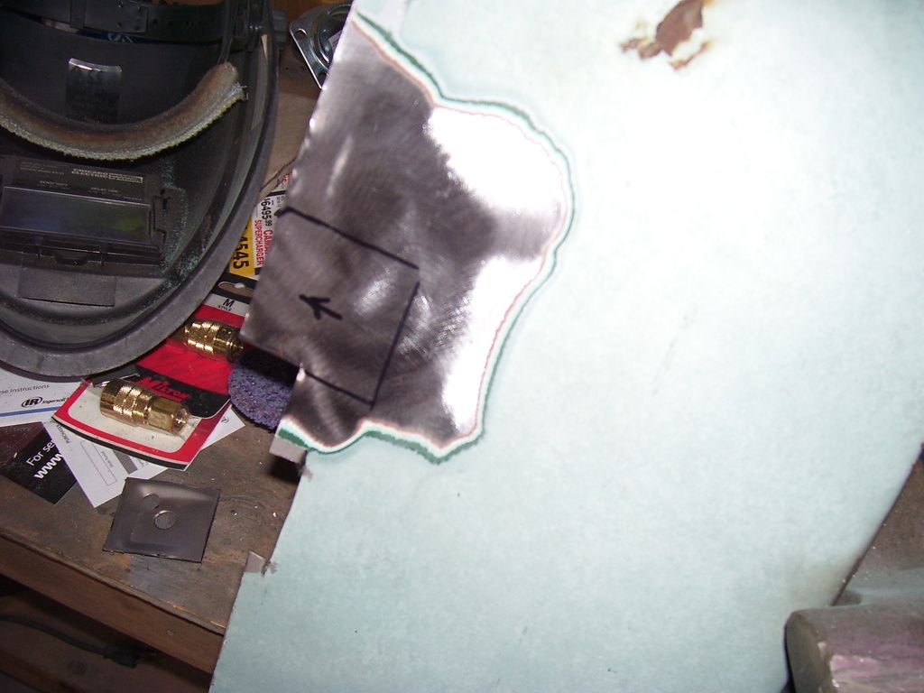
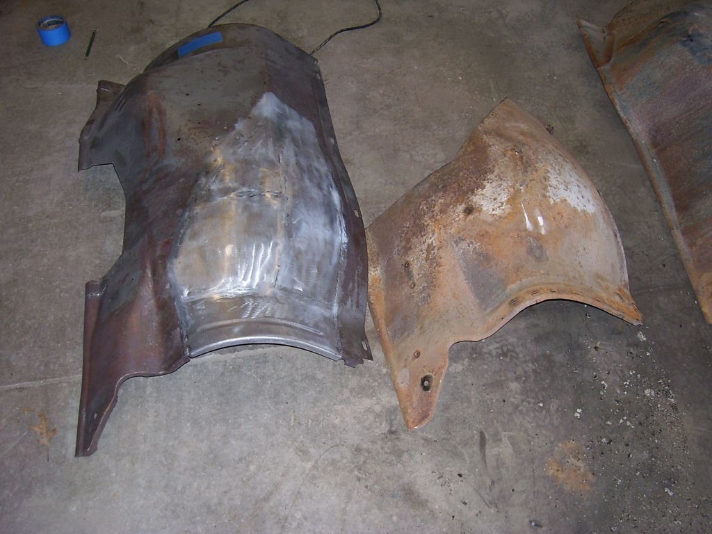
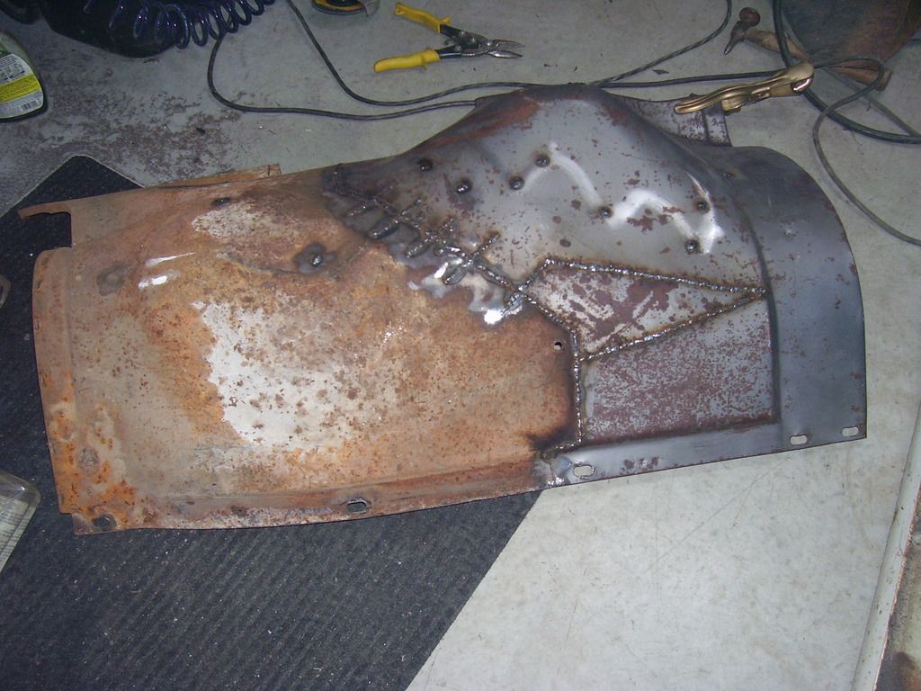
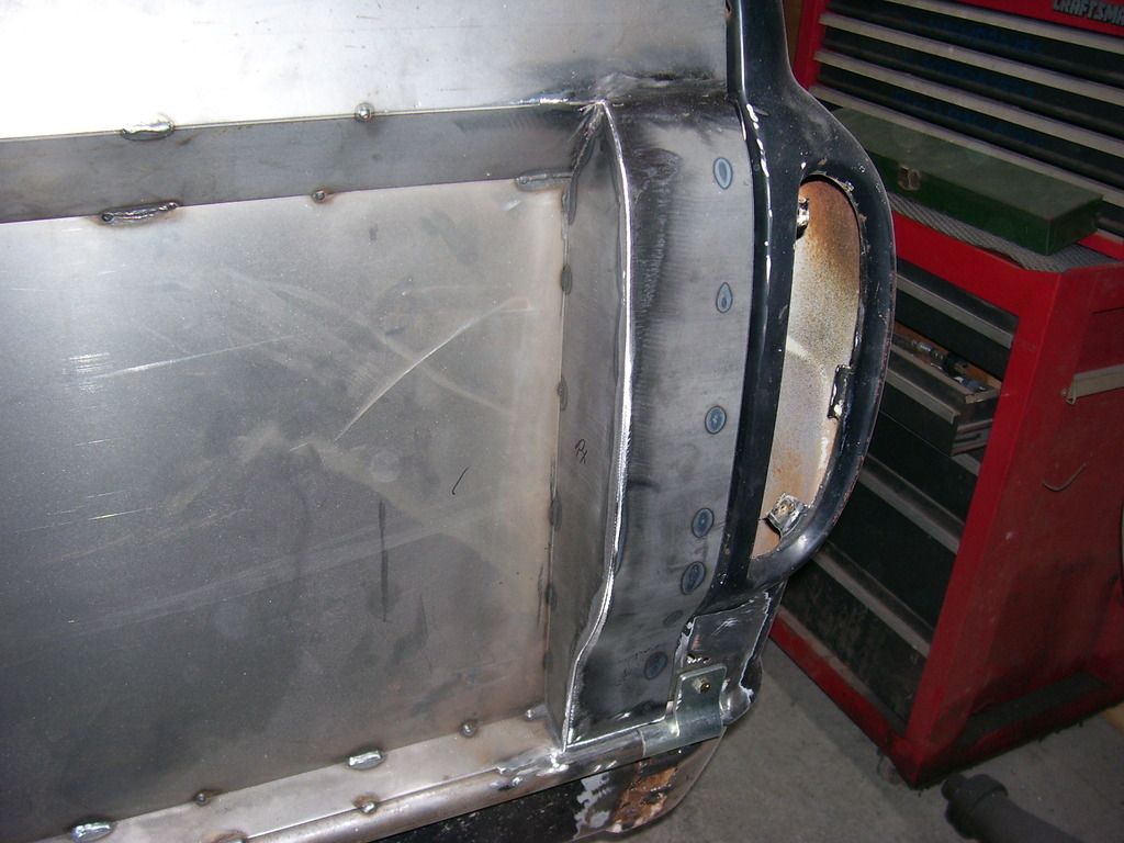
Here's the "jog" I put in the cut under the fender line to save the slotted fender mounting hole.
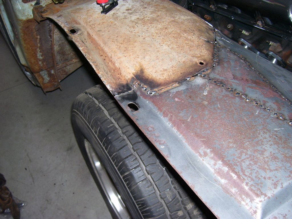
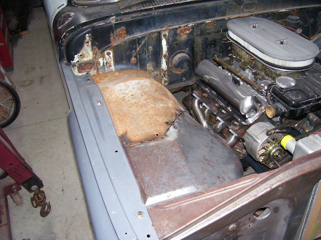
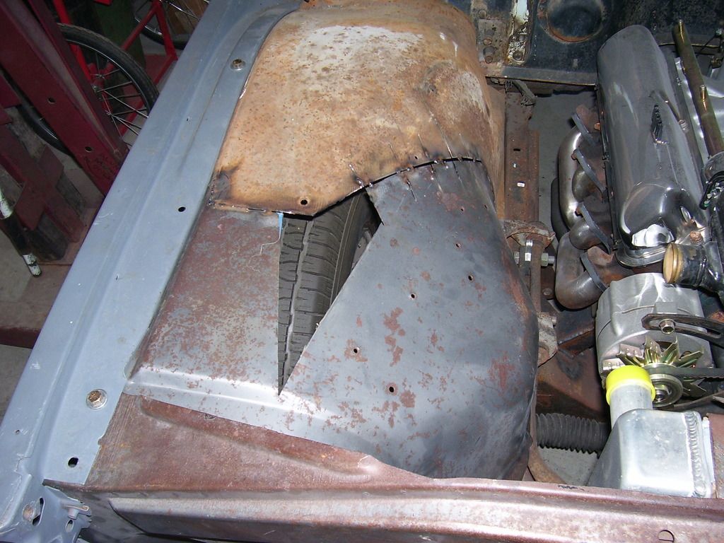
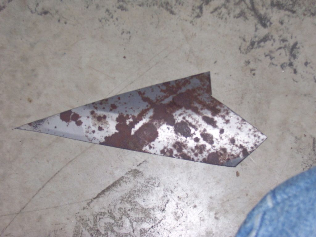
The area where the voltage regulator mounts makes a sharp break from the vertical face of the fender to the horizontal part. The left inner fender is a continuous crown thru that same area. The tape shows where that area is on the stock inner fender. My remedy to fix that was to cut it out and replace it with a new more rounded piece of metal.
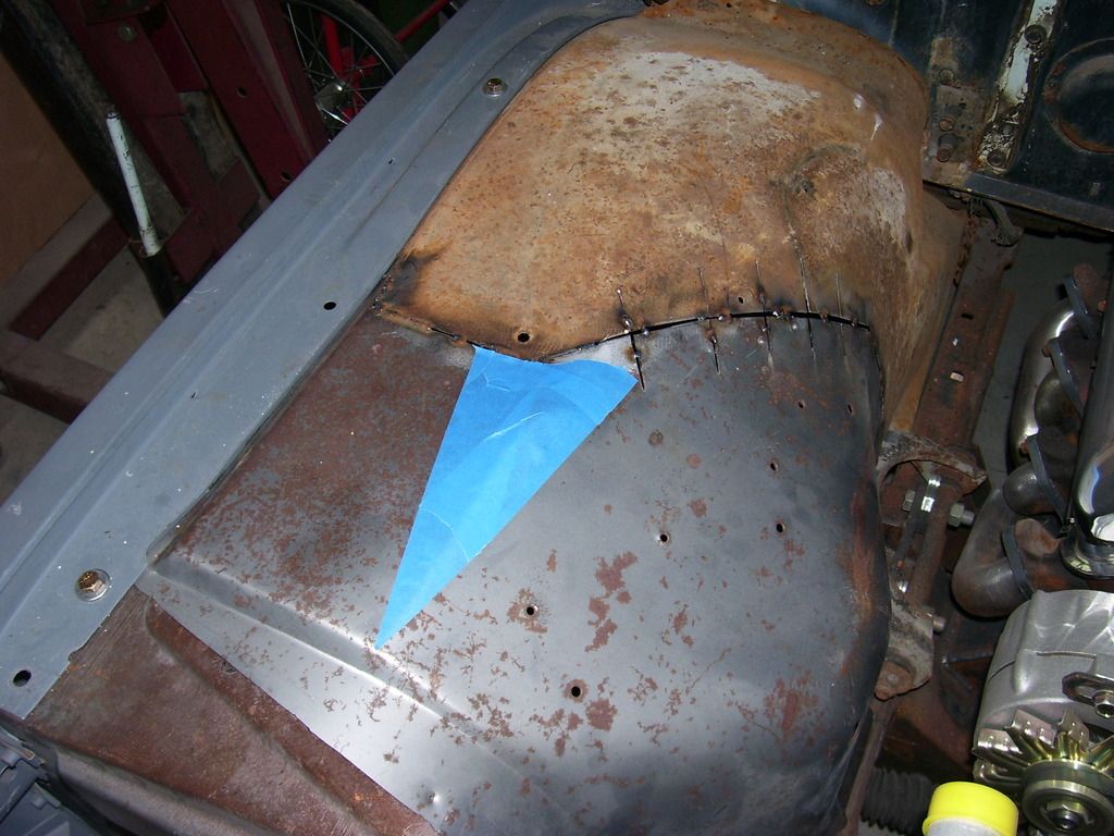
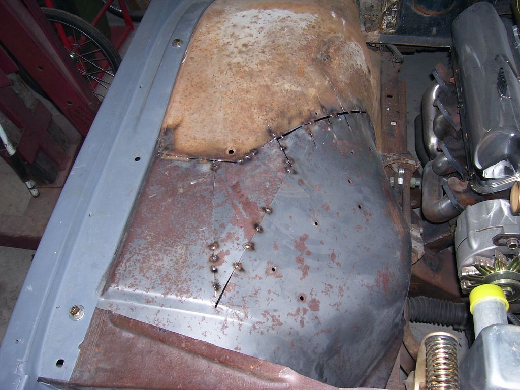
Once that was in, I welded everything solid. Also fixed a small rust area at the rear mount area.
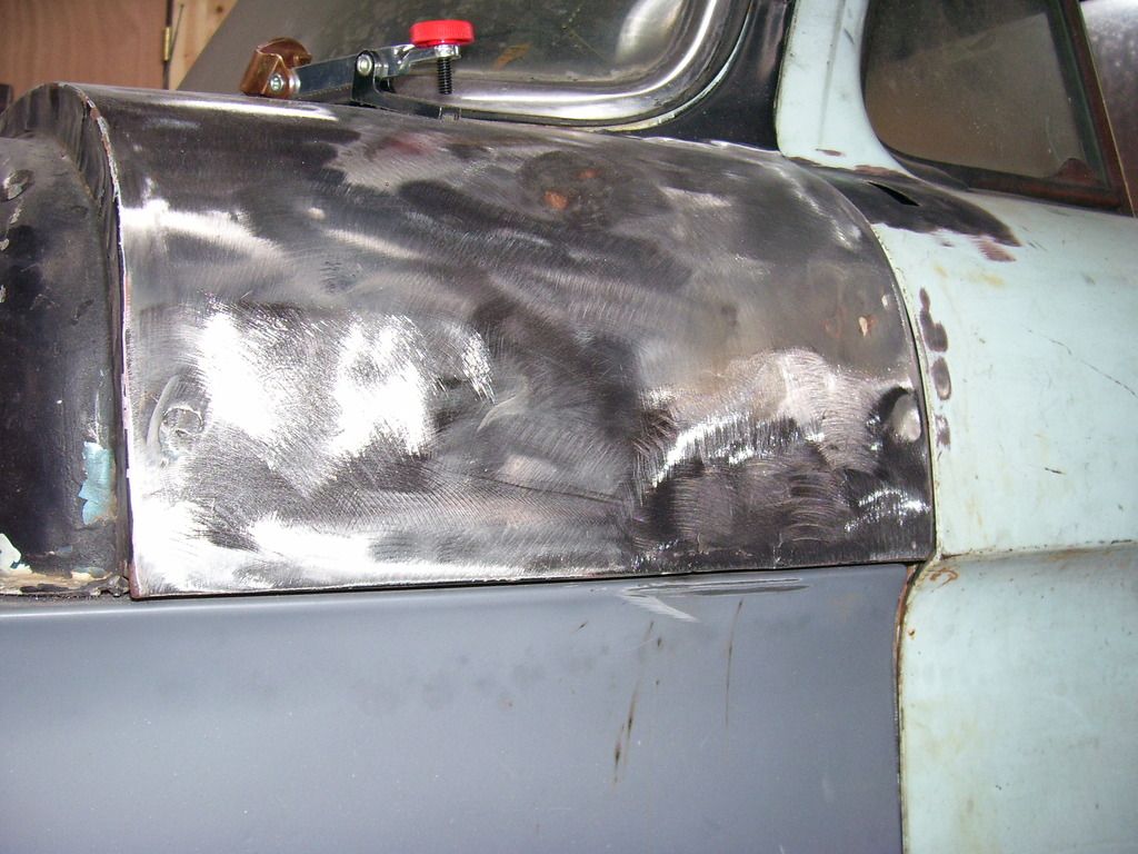
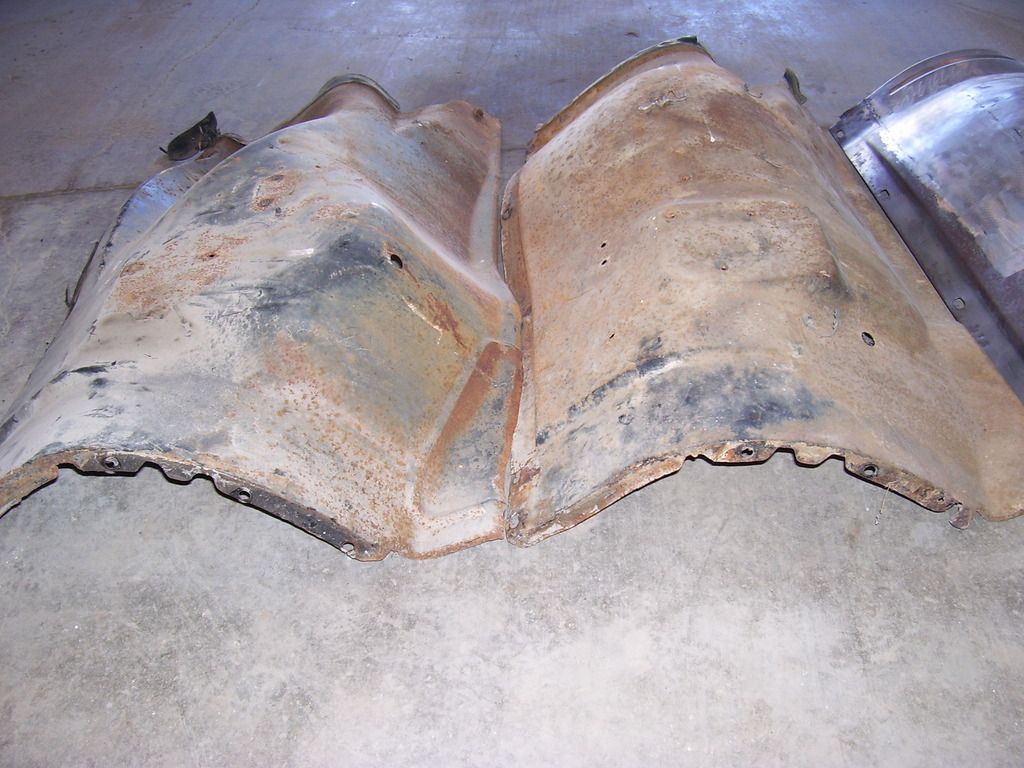
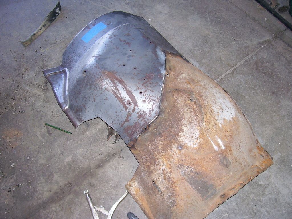
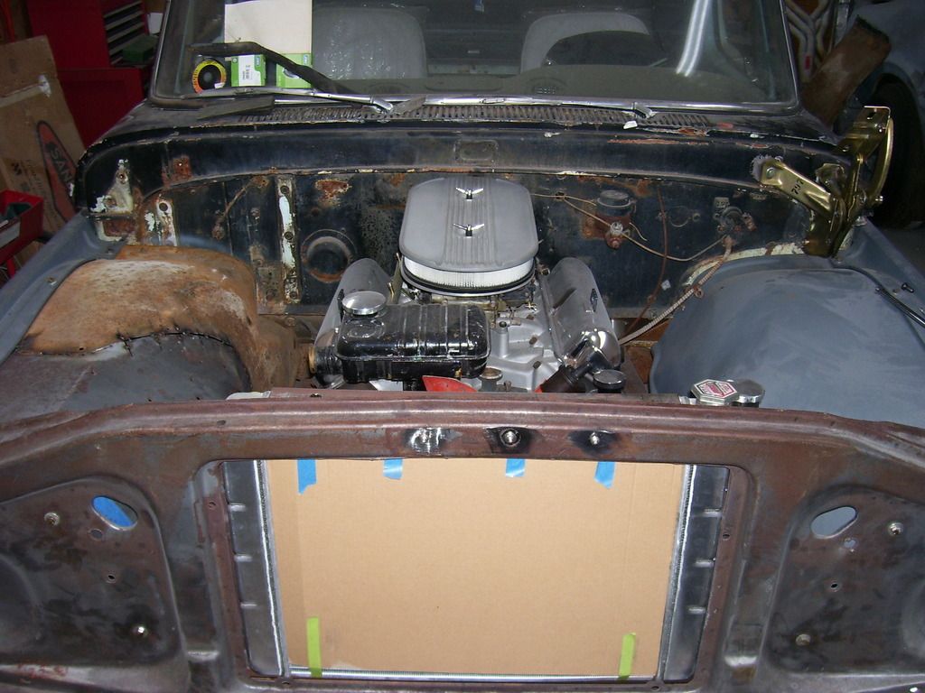
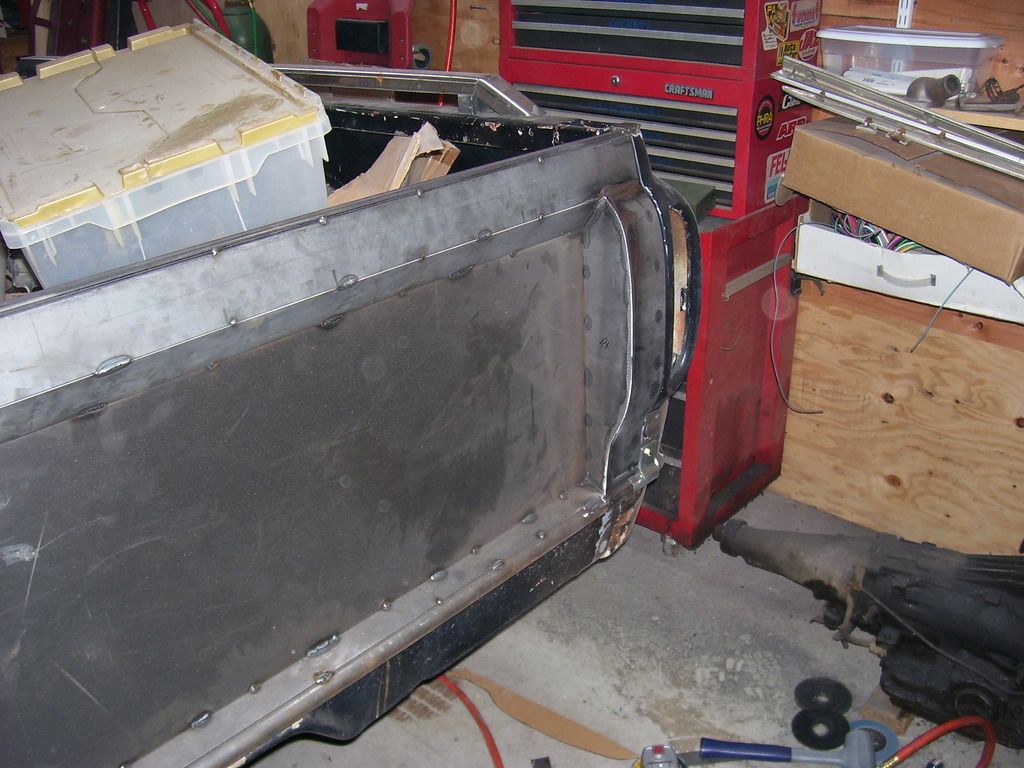
It was ground down and put back in and the fender mounted to make sure everything fit. The last 2 pictures show the original left (driver's side) and the newly modified right (passenger's side) inner fenders looking much more like mirror images of each other. No battery recess, no regulator mounting pad and all the holes filled in.
A tip on welding sheetmetal and avoiding warpage. I will weld an inch or so and blow the area cool with compressed air. It's a lot easier than using a wet rag to cool it. You can watch the metal return to it's original shape while the air blows across the surface and there is no water mess in your welding area. Also, make sure your sheetmetal doesn't butt against the piece you are welding it to. A slight gap to fill will leave you with a better seam than butting the 2 pieces up against each other solid. Need to allow for the expansion when welding or you will have more warpage.
SPark
Here's the "jog" I put in the cut under the fender line to save the slotted fender mounting hole.

The area where the voltage regulator mounts makes a sharp break from the vertical face of the fender to the horizontal part. The left inner fender is a continuous crown thru that same area. The tape shows where that area is on the stock inner fender. My remedy to fix that was to cut it out and replace it with a new more rounded piece of metal.


Once that was in, I welded everything solid. Also fixed a small rust area at the rear mount area.


It was ground down and put back in and the fender mounted to make sure everything fit. The last 2 pictures show the original left (driver's side) and the newly modified right (passenger's side) inner fenders looking much more like mirror images of each other. No battery recess, no regulator mounting pad and all the holes filled in.


A tip on welding sheetmetal and avoiding warpage. I will weld an inch or so and blow the area cool with compressed air. It's a lot easier than using a wet rag to cool it. You can watch the metal return to it's original shape while the air blows across the surface and there is no water mess in your welding area. Also, make sure your sheetmetal doesn't butt against the piece you are welding it to. A slight gap to fill will leave you with a better seam than butting the 2 pieces up against each other solid. Need to allow for the expansion when welding or you will have more warpage.
SPark
1932 Ford 5 window coupe. 302/C4
1962 8V-390/C6 Unibody Short Bed Soon to be Big Window - The Lincoln that never was
2013 F150 Super Crew Eco Boost 4x4
2015 Ford Edge for the little lady, because she said so!
2007 Mustang GT, 4.6-3V/5 Speed. Only 8680 miles on the clock.
More toys, I need more toys!!!
1962 8V-390/C6 Unibody Short Bed Soon to be Big Window - The Lincoln that never was
2013 F150 Super Crew Eco Boost 4x4
2015 Ford Edge for the little lady, because she said so!
2007 Mustang GT, 4.6-3V/5 Speed. Only 8680 miles on the clock.
More toys, I need more toys!!!
Re: '62 Unibody
A little rust and damage repair today.
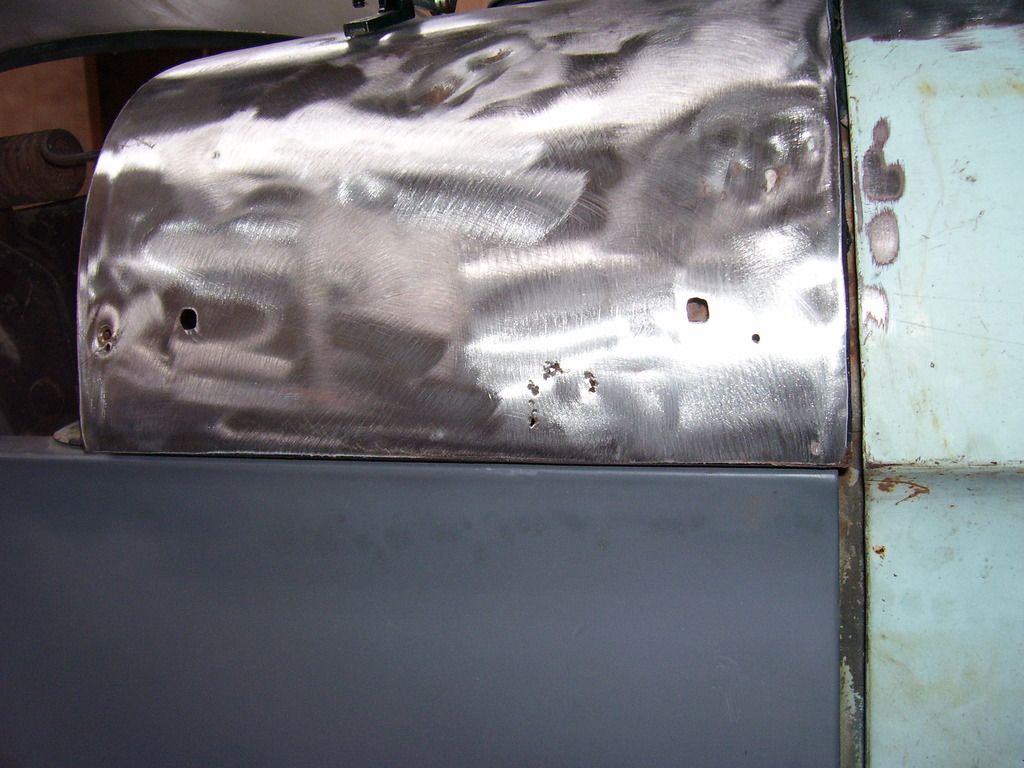
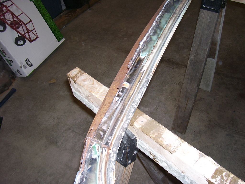
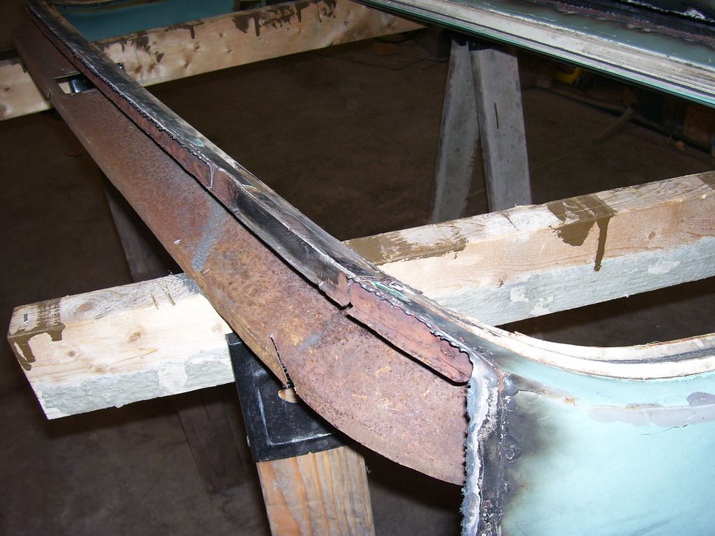
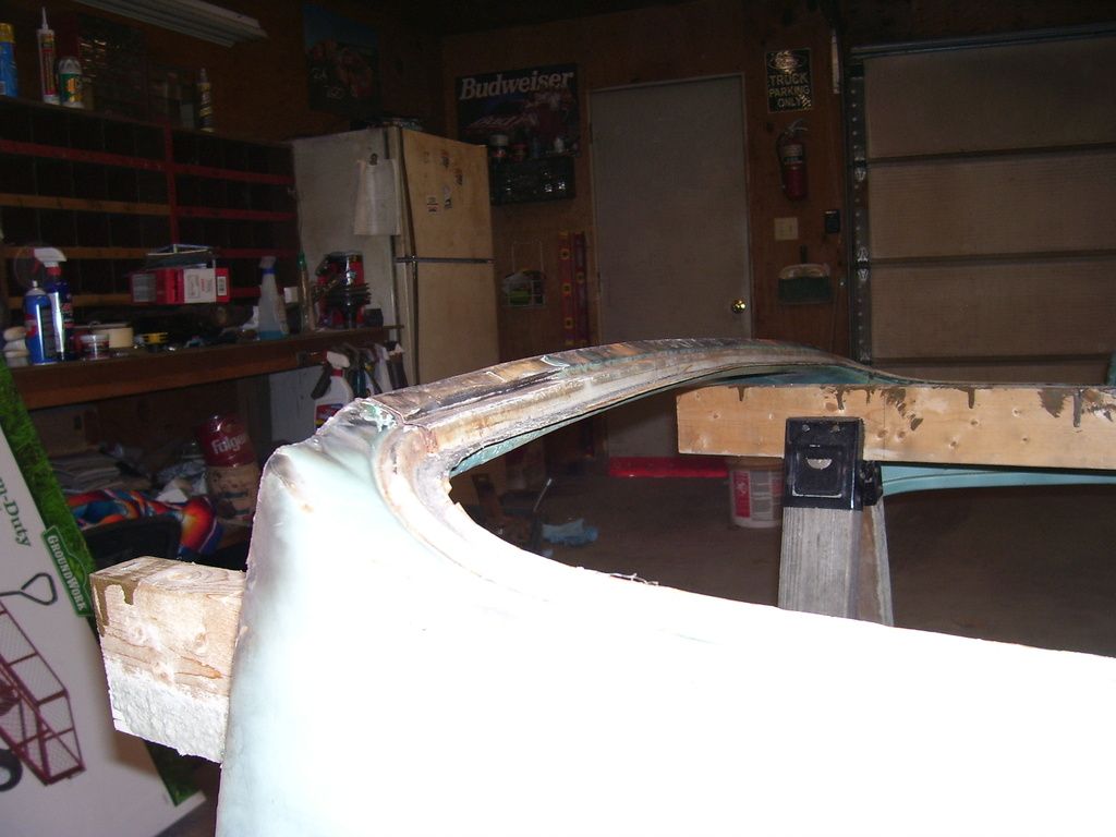
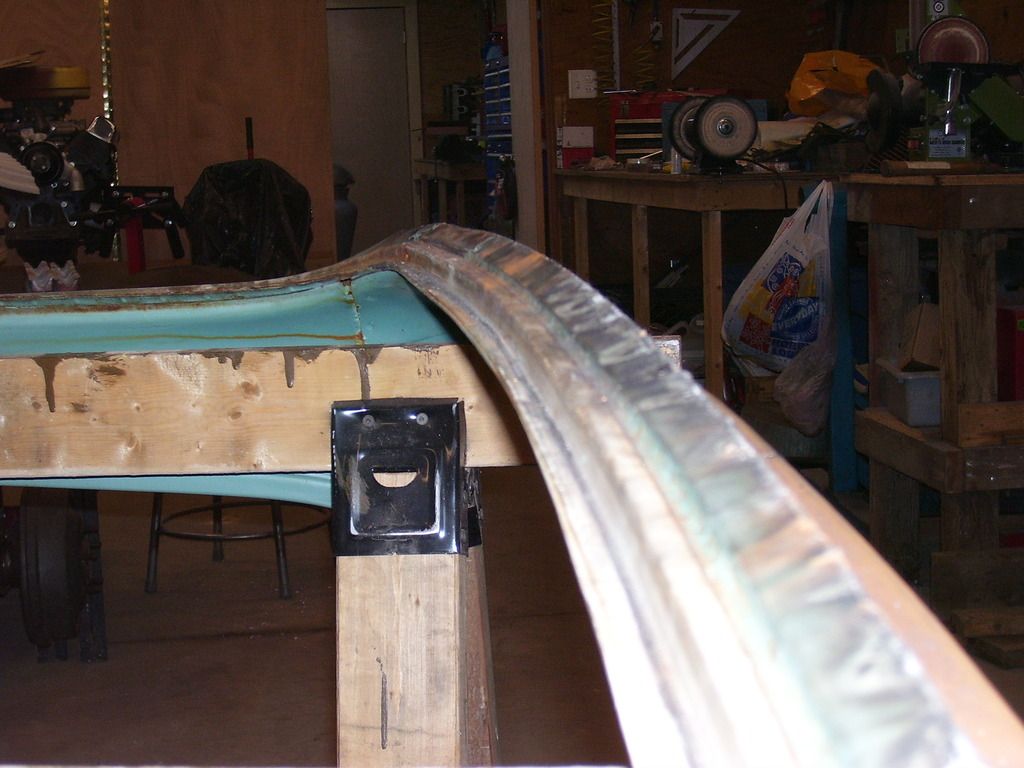
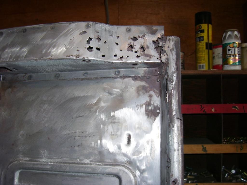
The big window section at some point in it's life had a tree limb fall on it. It had a pretty severe dent that pushed the pinch weld (that the window gasket attaches to) down almost 3/4" at the worst spot. It didn't look all that bad until you make a template from the other side to compare the arc of the opening to. Also, the majority of the rust in the section is contained in this one area.
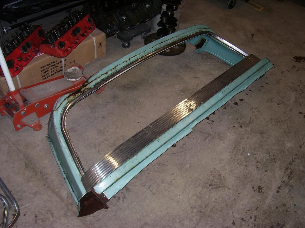
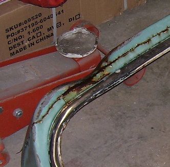
Decided to cut the top flange out (where it actually attaches to the roof skin), work the area with a hammer and dolly, get the shape back in and replace the rusty top flange. Was a bit harder getting the arc back in the pinch weld than I expected. Now the arc of the opening on both sides match left and right. Need a bit more work on the top edge but most of what remains there will be covered with weld and blending it to the top when it gets installed.
Now it's back to removing the un-needed metal around the opening. There must be 10,000 spot welds holding this piece together. It's also 3 to 4 layers thick in some areas. Really tired of spot welds.
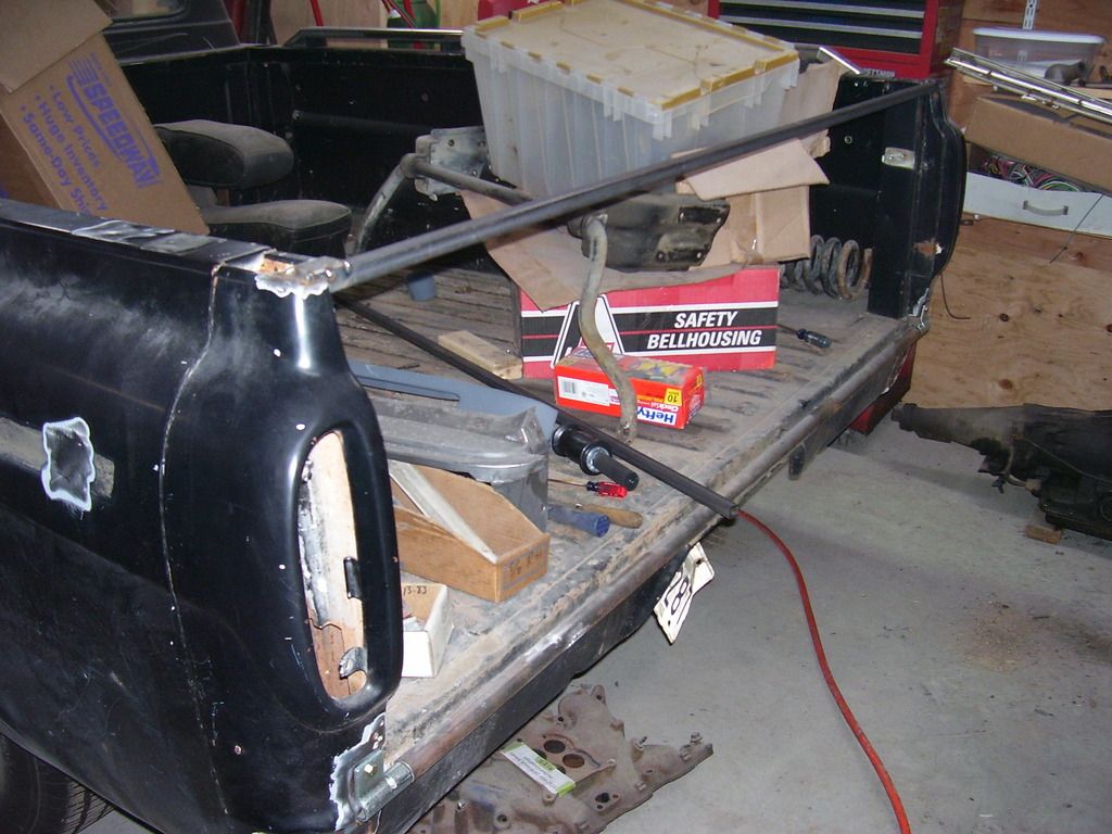
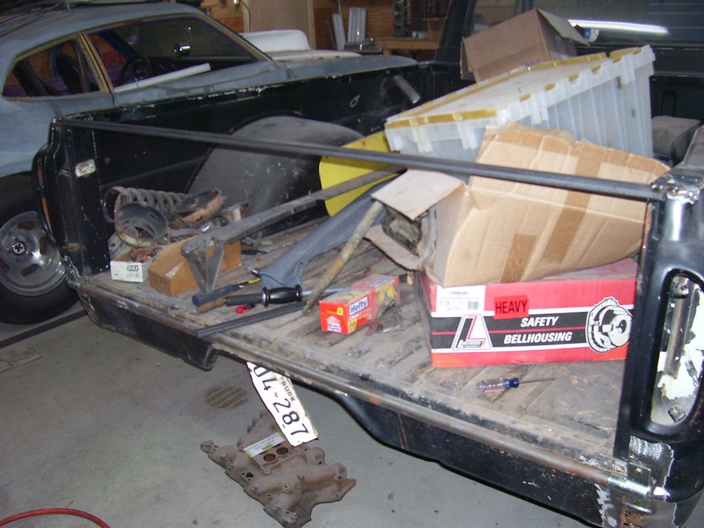
Also started on the new tailgate. The original was a rust bucket so it's nothing but a template now. In addition to being badly rusted, it's pretty badly bent. It doesn't show in the pictures but it's bowed almost 2" in the middle where the world was dropped on it.
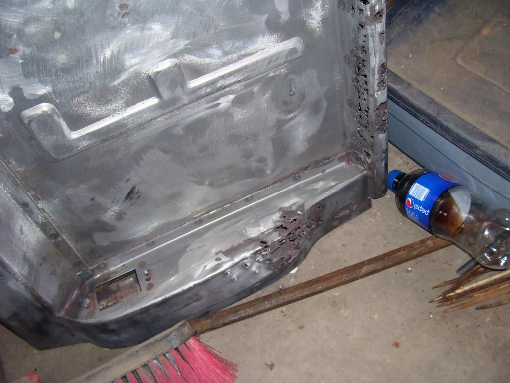
The new gate started. Got a new lower bar mounted on new hinges. The bar is sized so oilite bearings fit between the hinge pin and the inner dimension of the tubing. The top bar is a piece of 3/4" square tubing. I have a local blacksmith sheering 16 gauge sheetmetal to size. Going to build a smooth tailgate that mimics the shapes of the original but is a bit different in a few areas.
Hopefully have the sheetmetal by the end of the week and get going again!
SPark
The big window section at some point in it's life had a tree limb fall on it. It had a pretty severe dent that pushed the pinch weld (that the window gasket attaches to) down almost 3/4" at the worst spot. It didn't look all that bad until you make a template from the other side to compare the arc of the opening to. Also, the majority of the rust in the section is contained in this one area.


Decided to cut the top flange out (where it actually attaches to the roof skin), work the area with a hammer and dolly, get the shape back in and replace the rusty top flange. Was a bit harder getting the arc back in the pinch weld than I expected. Now the arc of the opening on both sides match left and right. Need a bit more work on the top edge but most of what remains there will be covered with weld and blending it to the top when it gets installed.


Now it's back to removing the un-needed metal around the opening. There must be 10,000 spot welds holding this piece together. It's also 3 to 4 layers thick in some areas. Really tired of spot welds.
Also started on the new tailgate. The original was a rust bucket so it's nothing but a template now. In addition to being badly rusted, it's pretty badly bent. It doesn't show in the pictures but it's bowed almost 2" in the middle where the world was dropped on it.


The new gate started. Got a new lower bar mounted on new hinges. The bar is sized so oilite bearings fit between the hinge pin and the inner dimension of the tubing. The top bar is a piece of 3/4" square tubing. I have a local blacksmith sheering 16 gauge sheetmetal to size. Going to build a smooth tailgate that mimics the shapes of the original but is a bit different in a few areas.


Hopefully have the sheetmetal by the end of the week and get going again!
SPark
1932 Ford 5 window coupe. 302/C4
1962 8V-390/C6 Unibody Short Bed Soon to be Big Window - The Lincoln that never was
2013 F150 Super Crew Eco Boost 4x4
2015 Ford Edge for the little lady, because she said so!
2007 Mustang GT, 4.6-3V/5 Speed. Only 8680 miles on the clock.
More toys, I need more toys!!!
1962 8V-390/C6 Unibody Short Bed Soon to be Big Window - The Lincoln that never was
2013 F150 Super Crew Eco Boost 4x4
2015 Ford Edge for the little lady, because she said so!
2007 Mustang GT, 4.6-3V/5 Speed. Only 8680 miles on the clock.
More toys, I need more toys!!!
Re: '62 Unibody
Just be glad you aren't installing long box BOX CORNERS on that shorty !
All those rusted areas on your tailgate stayed on the truck when I took my gate off that wreck at the yard.. however mine was pretty straight above so I had it easier than you there... just some bowing here and there in the tin between the FORD letters...
As to the inner passenger side splash pan.. Lots of work to make it look like it should have from the factory ! hahahahaha
Its funny how sometimes the least necessary projects can be the most satisfying.
Re: '62 Unibody
Finally got all the steel for the tailgate today.
First placed the lower return flange against the lower hinged round bar and tacked it in place. Once that was tacked in, I placed the main vertical tailgate panel so it rested on the just tacked lower return panel and rested against the front side of the 3/4" upper square bar.
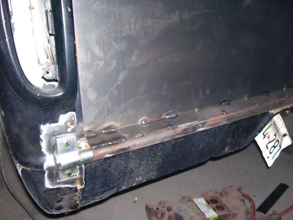
Once that was all solidly tacked in place, I put in the top rear panel. The angle on it matches the end caps for the box above the taillight area. Once that piece was tacked, I placed the return that attaches to it's lower edge and back to the main tailgate piece. That is the basic skeleton of the tailgate.
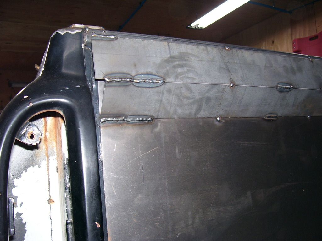
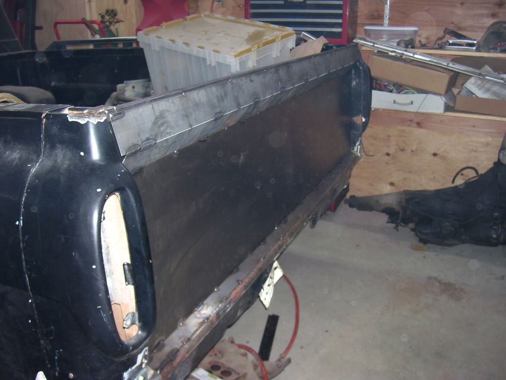
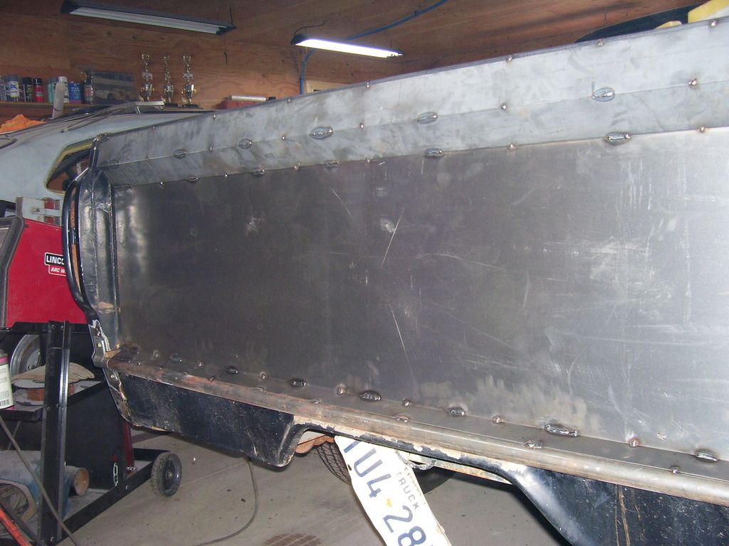
The next step was putting in the latch panels that match the bulge that houses the taillight. There are 2 of these on each side. Once they are all welded, I copied the profile of the end cap to these pieces, trimmed them to shape and welded the face plates in place. Once welded it was a little more grinding to finish the end pieces.
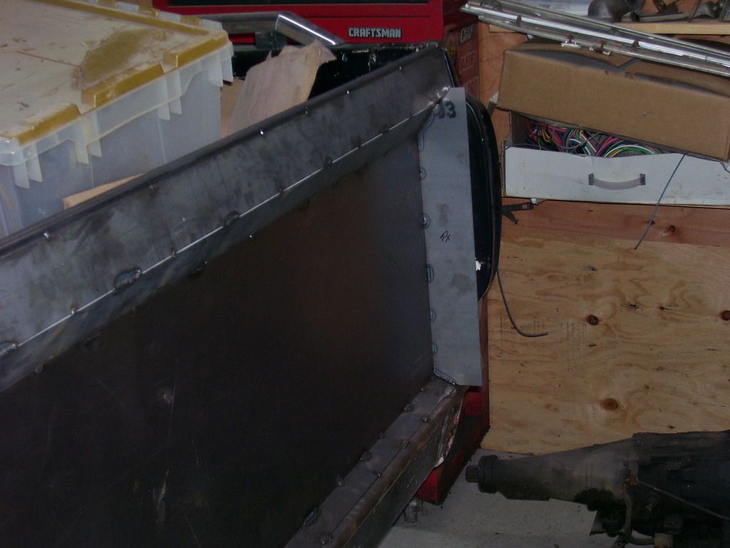
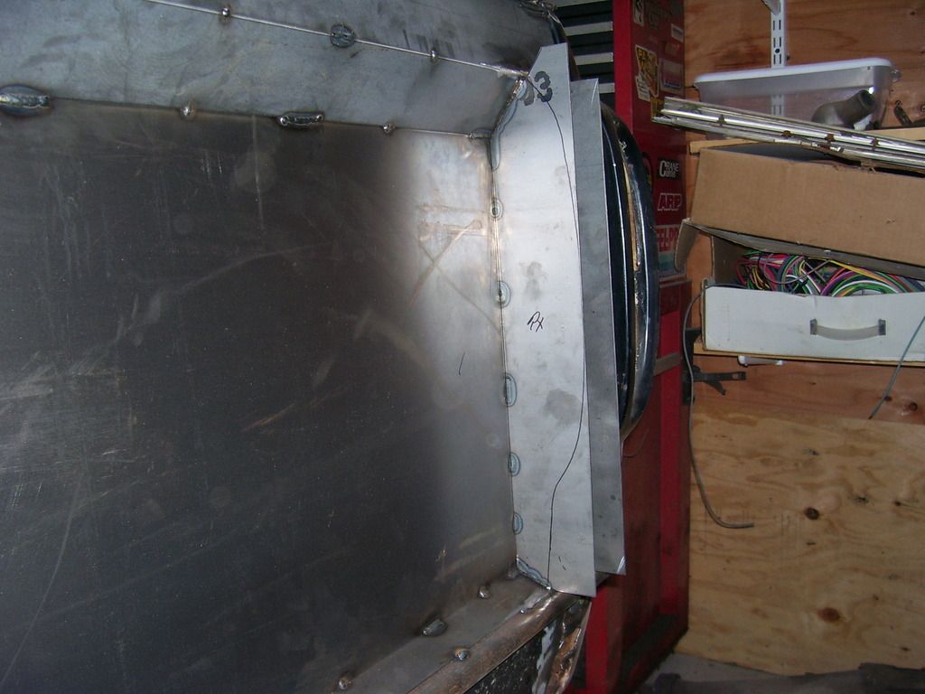
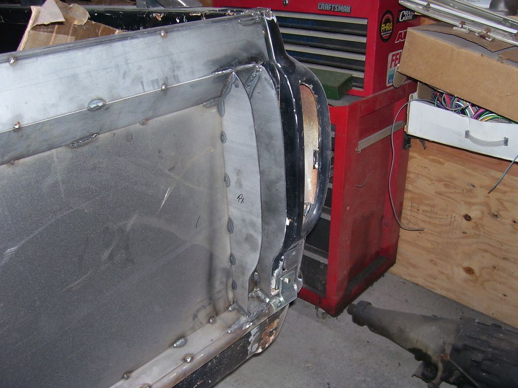
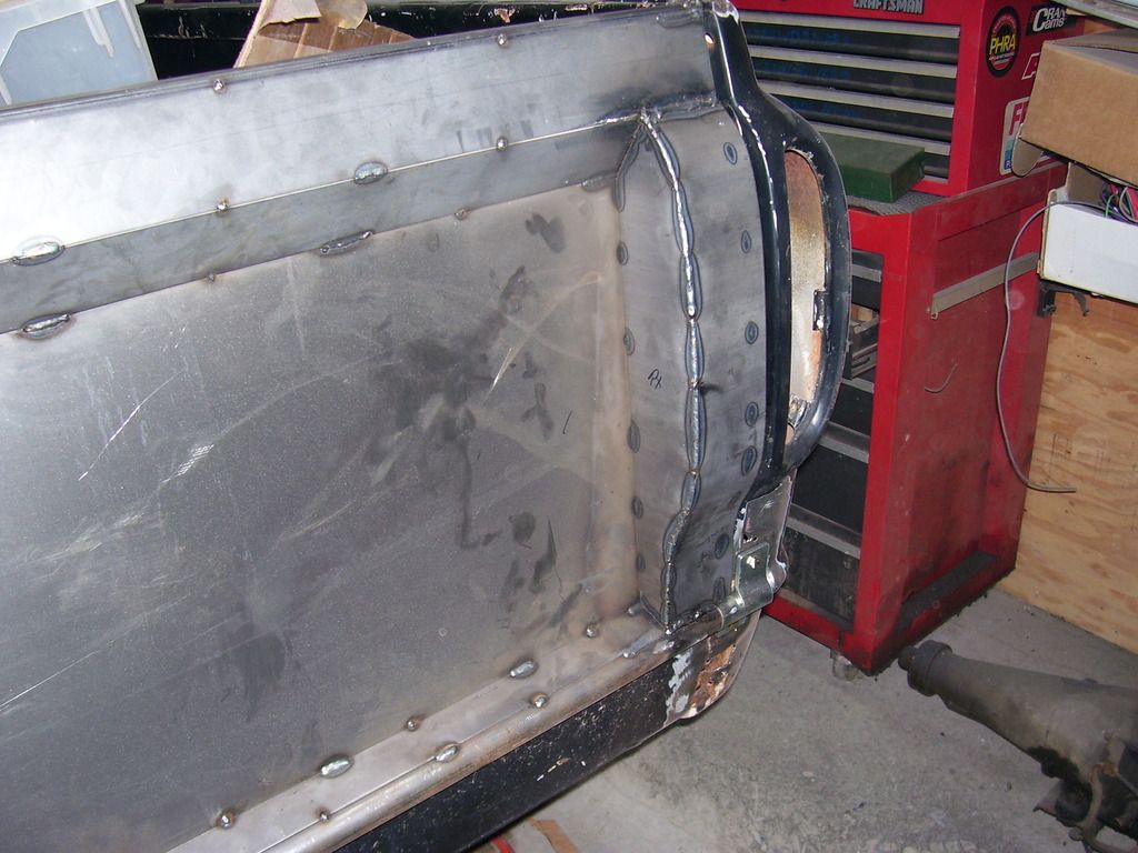
All basically built on the outside, now I need to finish the jamb area.
Another 4 or 5 hours of welding and grinding should have it looking a bit more complete. Working on a different system to latch it. I have all the stuff from the stock uni tailgate but think this needs something a little different.
Thanks for looking,
SPark
First placed the lower return flange against the lower hinged round bar and tacked it in place. Once that was tacked in, I placed the main vertical tailgate panel so it rested on the just tacked lower return panel and rested against the front side of the 3/4" upper square bar.

Once that was all solidly tacked in place, I put in the top rear panel. The angle on it matches the end caps for the box above the taillight area. Once that piece was tacked, I placed the return that attaches to it's lower edge and back to the main tailgate piece. That is the basic skeleton of the tailgate.


The next step was putting in the latch panels that match the bulge that houses the taillight. There are 2 of these on each side. Once they are all welded, I copied the profile of the end cap to these pieces, trimmed them to shape and welded the face plates in place. Once welded it was a little more grinding to finish the end pieces.


All basically built on the outside, now I need to finish the jamb area.


Another 4 or 5 hours of welding and grinding should have it looking a bit more complete. Working on a different system to latch it. I have all the stuff from the stock uni tailgate but think this needs something a little different.
Thanks for looking,
SPark
1932 Ford 5 window coupe. 302/C4
1962 8V-390/C6 Unibody Short Bed Soon to be Big Window - The Lincoln that never was
2013 F150 Super Crew Eco Boost 4x4
2015 Ford Edge for the little lady, because she said so!
2007 Mustang GT, 4.6-3V/5 Speed. Only 8680 miles on the clock.
More toys, I need more toys!!!
1962 8V-390/C6 Unibody Short Bed Soon to be Big Window - The Lincoln that never was
2013 F150 Super Crew Eco Boost 4x4
2015 Ford Edge for the little lady, because she said so!
2007 Mustang GT, 4.6-3V/5 Speed. Only 8680 miles on the clock.
More toys, I need more toys!!!