
These are the descriptions of where the wires go to coming out of the 42 pin connector at the engine and the pin numbers at the EEC. I spent a bunch hours with a continuity tester tracing them out so it might save somebody a bunch of time. It sure made the job easier.
This is the computer (EEC) wiring schematic.
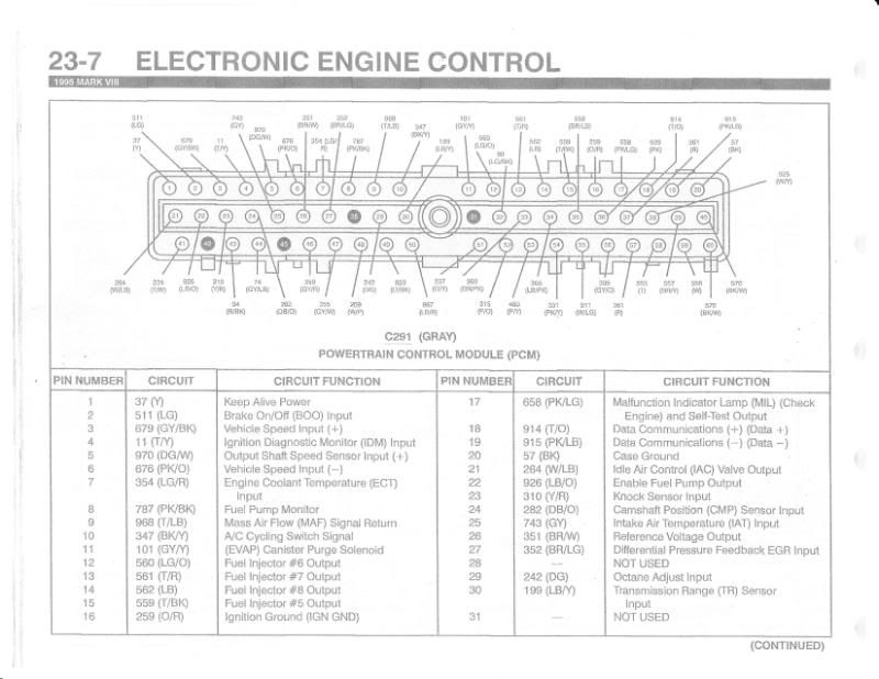
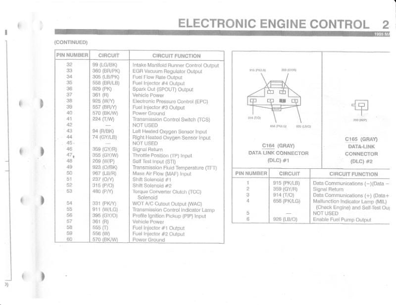
Here is the 42 pin connector
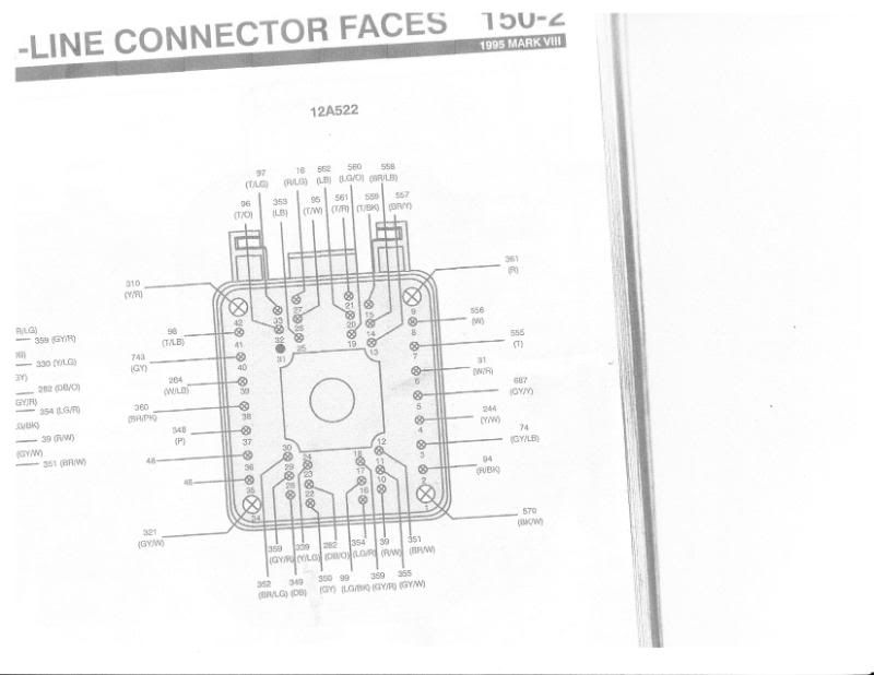
This is my description of where they all go.
42 Pin Connector From Engine Harness
For 95 Lincoln Mark VIII Plug # C118M
PIN / on engine – goes to
#1 - L & R O2 sensors – goes to EEC pin # 60, tees off to power ground and air filter box sensor
#2 – Left O2 sensor – goes to EEC pin # 43
#3 – Right O2 sensor – goes to EEC pin # 44
#4 – Sending unit on back of right head goes to cold lockout for A/C controls. I will change the sensor to a sending
unit for the electric fan relay.
#5 – L & R O2 sensors – goes to switched power supply
#6 – Oil pressure sending unit – goes to gauge
#7 – Fuel injector # 1 – goes to EEC pin # 58 injector # 1 output
#8 – Fuel injector # 2 – goes to EEC pin # 59 injector # 2 output
#9 – Multiple pieces on engine - Vehicle power goes EEC pin # 37 & 57, tees off ignition control module pin # 7
and the main transmission plug on the passenger side
#10 – Temperature sending unit, drivers side – goes to gauge
#11 – Throttle position sensor – goes to EEC pin # 47 throttle position input
#12 – Throttle position sensor – goes to EEC pin # 26 reference voltage output
#13 – Fuel injector # 3 – goes to EEC pin # 39 injector # 3 output
#14 – Fuel injector # 4 – goes to EEC pin # 35 injector # 4 output
#15 – Fuel injector # 5 – goes to EEC pin # 15 injector # 5 output
#16 – Temperature sending unit – goes to EEC pin # 7 engine coolant temp
#17 – Switch on left valve cover – goes to EEC pin # 32 intake manifold runner control output
#18 – L & R O2 sensors, engine temp sender, & throttle position sensor – goes to EEC pin # 24,29 & 46
#19 – Fuel injector # 6 – goes to EEC pin # 12 injector # 6 output
#20 – Fuel injector # 7 – goes to EEC pin # 13 injector # 7 output
#21 – Fuel injector # 8 – goes to EEC pin # 14 injector # 8 output
#22 – Negative crank position sensor – goes to ignition control module pin # 9
#23 – Cam position sensor – goes to EEC pin # 2 cam position sensor input
#24 – P/S pump – goes to EVO actuator on steering column DELETE
#25 – P/S pump – goes to EVO Actuator on steering column DELETE
#26 – Drivers side coil – goes to ignition control module pin #5 driver for ignition coil #1
#27 – Ignition coil condenser, drivers and passenger side – goes to fuel pump relay and tees off to fused power in
start & run
#28 – Positive Crank Position Sensor – goes to ignition control module pin # 8
#29 – Cam position sensor – goes to EEC pin # 46 signal return
#30 – EGR valve – goes to EEC pin # 27 differential pressure feedback EGR input
#31 – Not used
#32–Passenger side coil–goes to ignition control module pin #4 driver for ignition coil #2
#33–Passenger side coil–goes to ignition control module pin #2 driver for ignition coil #3
#34 – A/C compressor – goes to VCRM-a/c clutch coil return
#35 – goes to EEC pin # 20 case ground, tees off and goes to wire grounded on frame
#36 – Same as 35 above
#37 – A/C compressor – goes to VCRM-a/c clutch coil power
#38 – EGR vacuum control switch, left valve cover – goes to EEC pin # 33, EGR vacuum regulator output
#39 – Idle Air Control – goes to EEC pin # 21 idle air control valve output
#40 – Sensor in air intake after filter – goes to EEC pin # 25 air intake temp input (IAT)
#41 – Drivers side coil – goes to ignition control module pin #1 driver for ignition coil #4
#42 - Knock sensors under intake – goes to EEC pin # 23 knock sensor input
I kow this is long but it might be useful. I would think that some of this would transfer over to the 4.6L SOHC motor as well.
The scariest part is that I am actually starting to understand this mess.
The COP engines will probably be a little different.
Kevin